Mercedes-Benz Sprinter is a family of light-duty vehicles. The model with body index W906, also known as NCV3, was introduced in 2006. In 2013, the car went through a restyling. In this article, we will take a detailed look at the fuse box diagrams for the Mercedes Sprinter NCV3 (2nd Gen; body W906) 2006, 2007, 2008, 2009, 2009, 2010, 2010, 2011, 2012, 2013, 2013, 2014, 2015, 2015, 2016, 2017, 2018 years of manufacture.

Here you will find the locations and photos of distribution boxes. The fuses responsible for the “Cigarette lighter” and “Fuel Pump” are highlighted in bold.
In the passenger compartment
There are three distribution boxes here, which are responsible for protecting the vehicle's electrical circuits.
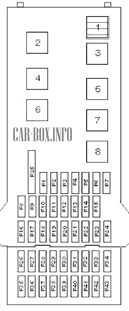
Fuse box #1 (main)
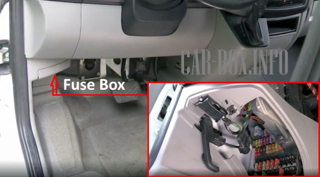
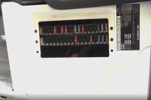
The main distribution box is located under the dashboard on the driver's side.
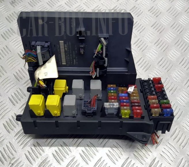
General view of the Mercedes Sprinter interior fuse box.
| Diagram | ||
|---|---|---|
|
||
| No. | Description | A |
| F1 | Horn (beep) | 15 |
| F2 | Spare | 25 |
| F3 | Spare | 10 |
| F4 | Spare | 5 |
| F5 | Windshield wiper | 30 |
| F6 | Fuel module (mercedes sprinter 906 fuel pump fuse) | 15 |
| F7 | Steering column electronics control unit | 5 |
| F8 | Engine management system | 20 |
| F9 | Engine management system | 20 / 25 |
| F10 | Engine management system | 10 |
| F11 | Main ignition circuits | 15 |
| F12 | SRS electronic control unit | 10 |
| F13 | Cigarette Lighter Fuse | 15 |
| F14 | Spare | 5 |
| F15 | Spare | 5 |
| F16 | Engine management system | 10 |
| F17 | SRS electronic unit | 10 |
| F18 | Spare | 7.5 |
| F19 | Interior lamps | 7.5 |
| F20 | Multifunctional control unit | 25 |
| F21 | Electronic engine control unit | 5 |
| F22 | ABS / ESP system | 5 |
| F23 | Starter | 20 / 25 |
| F24 | Engine management system | 10 |
| F25 | Accessory power connector | 25 |
| F26 | Door control unit, driver's side | 25 |
| F27 | Diagnostic connector (DLC) | 10 |
| F28 | ABS / ESP system | 25 |
| F29 | 40 | |
| F30 | Engine management system | 7.5 / 10 |
| F31 | Engine management system | 7.5 / 10 |
| F32 | Headlight washers | 30 |
| F33 | Spare | 15 |
| F34 | Direction indicators control unit | 10 |
| F35 | Audio system | 15/20 |
| F36 | Spare | 7.5 |
| F37 | Spare | 30 |
| F38 | Additional heater remote control receiver | 7.5 |
| F39 | Seat heater | 30 |
| F40 | Special vehicle equipment | 10 |
| F41 | Spare | 10 |
| F42 | Spare | 10 |
| F43 | Spare | 7.5 |
| No. | Relay | |
| 1 | Horn relay | |
| 2 | Wiper speed | |
| 3 | Fuel module (sprinter fuel pump relay) | |
| 4 | Turn on / off wipers | |
| 5 | Starter | |
| 6 | Spare | |
| 7 | Engine management system | |
| 8 | Spare | |
Fuse box #2
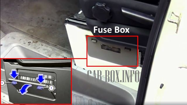
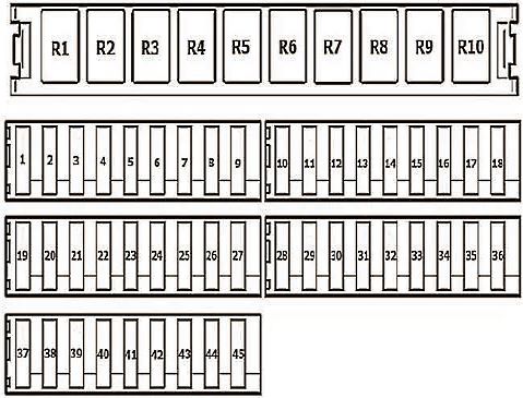
The second unit is located behind a protective cover under the driver's seat.
Access example.
| Diagram | ||
|---|---|---|
|
||
| No. | A | Appointment |
| 1 | 5 | Mirror position control, rear window heater relay |
| 2 | 30 | Rear wiper |
| 3 | 5 | Heater timer, reversing video camera, switch to neutral gear (with hill start assist system, all-wheel drive and engine continuation function), electrical equipment for retrofit - DIN socket (roof), FleetBoard system, anti-theft system with vehicle tracking, emergency hammer light in rear of vehicle, emergency exit light |
| 4 | 7.5 | Tachograph, automatic speed regulation (ADR), power take-off, trailer coupling (AAG) |
| 5 | 10 | Gearshift system control unit (EGS), terminal 87 |
| 5 | ECO engine start, engine off function, hood switch | |
| 6 | 5 | Four-wheel drive |
| 10 | All-wheel drive, ground clearance control (ENR), auxiliary oil pump | |
| 7 | 7.5 | Automatic transmission control lever module (EWM) |
| 10 | ||
| 15 | ||
| 8 | 10 | Dump truck with three-way tipping / load board, terminal 15, PARKTRONIC |
| 9 | 15 | SGU / roof fan |
| 7.5 | Air conditioning compressor clutch, deactivatable warning buzzer for reversing warning light | |
| 10 | 25 | Body equipment, terminal 30 |
| 11 | 15 | Body equipment, terminal 15 |
| 12 | 10 | Body equipment, terminal D + |
| 13 | 10 | Additional module of turn signal indicators (up to 03/07) |
| 30 | Air conditioning in the rear of the cabin | |
| 20 | Fuel pump FSCM (fuel level control module) | |
| 15 | Fuel pump relay without FSCM (vehicles with code MI6 / XM0) | |
| 14 | 20 | Trailer socket |
| 15 | 25 | Trailer coupling (AAG) |
| 16 | 7.5 | Tire Pressure Monitoring System (RDK), Parktronic |
| 17 | 25 | Control unit for parameterized special module (PSM) |
| 18 | 25 | Control unit for parameterized special module (PSM) |
| 19 | 5 | Overhead control unit (DBE) |
| 10 | ||
| 25 | Tilt-slide sunroof, overhead control unit (DBE) | |
| 10 | ERA-GLONASS system | |
| 20 | 7.5 | Parking lights, license plate light, identification light |
| 21 | 30 | Rear window heating without EDW (anti-theft alarm system) |
| 15 | Rear window heating with EDW (anti-theft alarm system) | |
| 22 | 15 | Rear window heating |
| 20 | Vehicle power socket | |
| 23 | 10 | Body electrical equipment, third party manufacturer |
| 15 | Power socket in the rear part of the passenger compartment on the left side | |
| 24 | 15 | Driver's seat box socket |
| 25 | 15 | Power socket in the rear part of the passenger compartment on the right side |
| 26 | 25 | Additional liquid heater |
| 27 | 25 | Additional heater |
| 20 | Additional air heater | |
| 28 | 30 | Rear air conditioning (until 03/07) |
| 7.5 | CNG, terminal 87 | |
| 25 | Starter relay SRB (fuse and relay box; vehicles without back-up battery) | |
| Starter with on-board mains support due to additional battery pack | ||
| 29 | 10 | Four-wheel drive |
| 30 | ||
| 7.5 | Terminal 87 (7) Gas fuel system, vehicles with NGT engine | |
| 30 | 30 | Air suspension (compressor), brake booster (for North America) |
| 10 | All wheel drive (compressor) | |
| 15 | Additional heat exchanger fan | |
| 31 | 15 | Sliding door on the left, fan in the rear of the cabin |
| 30 | ||
| 15 | Sliding door closing mechanism reinforcement, left side | |
| 32 | 10 | Keyless Entry |
| 5 | SCR system - exhaust gas neutralization system control relay | |
| 33 | 30 | Right sliding door, suspension unit (ENR) |
| 15 | Sliding door closing mechanism reinforcement, right-hand side | |
| 34 | 30 | Left sliding door (until 03/07) |
| 20 | SCR system - 1 heating system, AdBlue® reductant, vehicles with diesel aftertreatment system | |
| 35 | 30 | Brake booster |
| 5 | SCR system - 2 heating system, AdBlue® reductant, vehicles with diesel aftertreatment system | |
| 36 | 15 | SCR system - control and heating system 3, AdBlue® reductant, vehicles with diesel aftertreatment system |
| 37 | 5 | COLLISION PREVENTION ASSIST / FCW (Front Collision Warning) |
| Lane Change Alarm / BSM (Blind Spot Monitoring System) | ||
| 38 | 10 | Multifunctional video camera (MK) with adaptive high beam headlights with lane departure warning |
| 39 | 7.5 | Body electrical equipment (distribution service), reinforced air conditioning system at the rear of the vehicle |
| 15 | Ceiling fan, siren | |
| 40 | 15 | Charging current from buffer battery (vehicles with buffer battery) |
| 41 | 7.5 | SAM (signal acquisition and excitation module) reference voltage of the storage battery |
| 42 | 30 | Rear air conditioning |
| 43 | 10 | Electric footrest / sliding door, right side |
| 44 | 10 | Electric footrest / sliding door, left side |
| 45 | 5 | Electric footrest, control module and warning buzzer |
| No. | Relay | |
| R1 | circuit. D + body manufacturer | |
| R2 | circuit. 15 body builders | |
| R3 | lighting | |
| load board | ||
| R4 | headlight washer | |
| R5 | Flashing Light | |
| R6 | EDW horn (EDW - anti-theft alarm system) | |
| R7 | Empty | |
| R8 | SSU | |
| R9 | circulation pump | |
| R10 | Empty | |
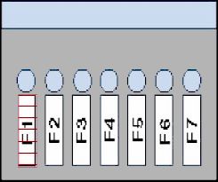
Power fusible links
The panel with them is located in the footwell.
| Diagram | ||
|---|---|---|
|
||
| No. | Appointment | A |
| F1 | Diesel: Glow plug control unit | 80 |
| F2 | Air conditioner | 40 / 60 |
| F3 | Multifunctional control unit | 80 |
| F4 | Optional rechargeable battery | 150 |
| F5 | Battery power distribution | 150 |
| F6 | Reserve | - |
| F7 | Additional heater | 150 |
All electrical equipment
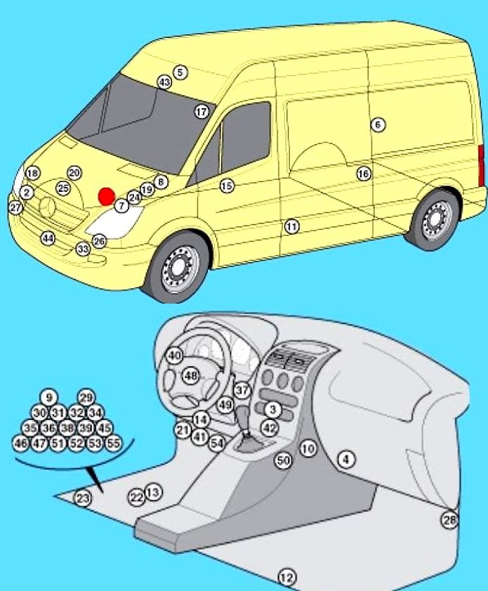
General layout of electronic components in Mercedes Sprinter W906.
1. ABS electronic unit;
2. Air conditioner condenser fan relay;
3. Air conditioner control module - in the heater control panel;
4. Air conditioner/heater fan control module - next to the fan motor;
5. Antenna amplifier;
6. Air suspension control module - rack "0";
7. Anti-theft alarm siren - engine compartment, left side;
8. Additional battery - engine compartment, left side;
9. Relay for auxiliary battery;
10. Auxiliary heater control module (type 1);
11. Auxiliary heater control module (type 2);
12. Auxiliary heater control module (type 3) - in the heater unit;
13. BATTERY;
14. Diagnostic connector (DLC);
15. Driver's side door electrical control module;
16. Left rear door electrical control module;
17. Right rear door electrical control module;
18. Engine ECU (Diesel) - Engine 651;
19. Engine ECU (Diesel) - except engine 651;
20. Engine ECU (Gasoline) - on the engine;
21. Fuse/relay box, passenger compartment instrument panel;
22. Fuse/relay box, in the footwell;
23. Fuse/relay box, under the seat;
24. Glow plug control module - engine 646;
25. Glow plug control module - except engine 646;
26. Headlight control module, left side (xenon);
27. Headlight control module, right side (xenon);
28. Headlight correction control module - A-pillar;
29. Rear window heater relay 1;
30. Rear window heater relay 2 (with anti-theft system);
31. Windshield heater relay.
