In 2018, Mercedes-Benz introduced the third generation of the Sprinter van. The model was presented in 6 body variants, the engine has two versions - 2.1 liters and 3 liters. In this article, we will take a detailed look at the fuse box diagrams for the Mercedes Sprinter (3rd gen; body W907 / W910) 2018, 2019, 2020, 2021, 2022, 2023 years of manufacture.

Here you will find the locations and photos of distribution boxes. The fuse responsible for the “cigarette lighter” is highlighted in bold.
In the cabin
There are three distribution boxes here, which are responsible for protecting the vehicle's electrical circuits.
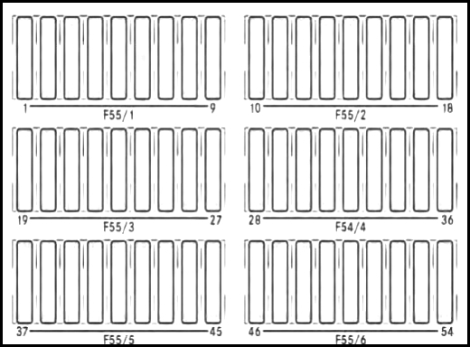
Fuse box #1
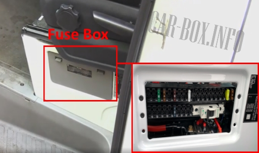
Located at the bottom of the driver's seat, behind the protective cover.
| Diagram | ||
|---|---|---|
|
||
| No. | Description | Amps |
| F55/1 board | ||
| 1 | Additional turn signal lamp | 10 |
| 2 | Rear window wiper right | 15 |
| 3 | Four-wheel drive | 30 |
| 4 | Terminal block for electrical connection | 25 |
| 5 | driver's seat adjustment | 25 |
| 6 | driver's seat heating | 10 |
| 7 | Driver's lumbar support | 25 |
| 8 | Tire pressure monitoring | 5 |
| 9 | Parking assistant; Main camera (RVC). | 5 |
| F55/2 board | ||
| 10 | Trailer hitch right (trailer socket) | 25 |
| 11 | Trailer socket control unit | 15 |
| 12 | Left hitch (trailer socket) | 25 |
| 13 | Trailer socket control unit | 15 |
| 14 | Multi Function Module (MPM) | 25 |
| 15 | 25 | |
| 16 | Rear camera blower | 25 |
| 17 | Additional heating | 20 |
| 18 | Automatic transmission, additional oil pump | 15 |
| F55/3 board | ||
| 19 | parking heating | 15 |
| Terminal 15 on the auxiliary battery. | ||
| 20 | Auxiliary battery | 5 |
| 21 | Left rear window heater | 15 |
| 22 | Right rear window heater | 15 |
| 23 | Hydroboard / tipper (before installation) | 7.5 |
| 24 | Terminal block for electrical connection | 15 |
| 25 | roof fan relay | 5 |
| 26 | Special signal | 7.5 |
| 27 | Rear window heating | 30 |
| F55/4 board | ||
| 28 | Sliding door on the left; | 15/30 |
| 29 | Right sliding door | 15/30 |
| 30 | Antenna switch unit | 5 |
| 31 | Automatic transmission | 7.5 |
| 32 | 10 | |
| 33 | brake booster | 30 |
| 34 | Siren relay; Preparing for a motorhome. | 15/30 |
| 35 | A flashing beacon with a siren; | 15/30 |
| Trailer | 30 | |
| 36 | Trailer | 30 |
| F55/5 board | ||
| 37 | Electric step left | 10 |
| 38 | Electric footboard right | 10 |
| 39 | Warning buzzer; | 5 |
| Electric step, right and left. | ||
| 40 | Automatic transmission (NAT2) | 10 |
| 41 | Terminal 15 special signal | 5 |
| 42 | Interior Mirror with Rear View Monitor, Rear View Camera (RVC); | 5 |
| 43 | Power socket, cab | 15 |
| 44 | Power connector, D-pillar, left | 15 |
| 45 | Power connector, D-pillar, right | 15 |
| F55/6 board | ||
| 51 | USB port, left | 5/7.5 |
| 52 | USB port, right | 5/7.5 |
Fuse box #2
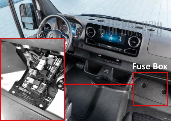
It is located behind the trim in the front passenger footwell. To access it, unscrew the two mounting screws, remove the cover and trim.
| Diagram | ||
|---|---|---|

|
||
| No. | Description | Amps |
| R1 | Reserve | 30 |
| R2 | Terminal 87, motor | 50 |
| R3 | Terminal 87 Common Drive Module (CPC) | 30 |
| R4 | Terminal 15-1 | 40 |
| R5 | Wipers (on / off) | 40 |
| R6 | Reserve | 40 |
| R7 | Wipers (speed) | 40 |
| R8 | Terminal 50 starter | 40 |
| R9 | Terminal 15R (vehicles without auxiliary battery) | 50 |
| R10 | Terminal 15-2 | 30 |
| R11 | Terminal 15R (vehicles without auxiliary battery) | 50 |
| MF1 board | ||
| 15-1 | ESP system module, four-wheel drive, air suspension, CPC transmission, Engine Control Unit; | 5 |
| MF2 board | ||
| 15-2 | Reversing alarm cut-off, PTO, operating speed control; active brake booster sensor, Headlight angle adjustment, Halogen headlight, Tachograph, Feedback cable, Relay terminal 15; | 5 |
| MF3 board | ||
| 30-T | Terminal 15, minimum voltage relay; Instrument panel, DIN connector, Central oil pump, Tachograph, Multifunction camera; | 7.5 |
| S9 board | ||
| 1 | empty | - |
| 2 | Common Transmission Module (CPC) | 10 |
| 3 | Engine control unit OM642 / OM651 / M274 | 10 |
| 4 | DIN connector, cab | 7.5 |
| 5 | Common Transmission Module (CPC) | 10 |
| 6 | Radiator fan (not for OM654) | 5 |
| S10 board | ||
| 7 | Automatic transmission | 30 |
| 8 | body controller | 30 |
| 9 | 30 | |
| 10 | Heated, SCR catalytic converter. | 30 |
| 11 | Ceiling control module | 15 |
| 12 | Pump, SCR catalytic converter. | 15 |
| S11 board | ||
| 13 | Automatic transmission NAT3 | 60 |
| S12 board | ||
| 14 | ESP valves, vehicles with electromechanical parking brake; | 25 / 40 |
| S13 board | ||
| 16 | ESP pump | 60 |
| S14 board | ||
| 17 | body controller | 30 |
| 18 | 30 | |
| 19 | Terminal block for bodybuilder electrical connection | 10 |
| 20 | Front passenger door control unit | 25 |
| 21 | Driver door controller | 25 |
| 22 | Air Suspension Control Unit (LFA) | 10 |
| S15 | ||
| 23 | Fan control unit | 25 |
| 24 | USB socket (cockpit, glove box); 115/230V inverter socket. | 7.5 |
| 25 | Cigarette lighter fuse Mercedes Sprinter W907 / W910, center console | 15 |
| 26 | Information panel socket | 15 |
| 27 | Inverter socket, 115V / 230V. | 25 |
| 28 | radio settings; Antenna; Inverter socket 115 V / 230 V | 7.5 |
| S16 board | ||
| 30-1 | empty | - |
| 30-2 | empty | - |
| 30-3 | central locking system | 5 |
| 30-4 | Signaling (ATA) | 5 |
| 30-5 | empty | |
| 30-6 | Electronic ignition lock control unit | 10 |
| 31 | Start, relay contact 15-II | 25 |
| S17 board | ||
| 32 | empty | - |
| S18 board | ||
| 33 | Voltage quality sensor (SEB) | 5 |
| S19 board | ||
| 34 | Electronics for interior lighting | 10 |
| - S1 | ||
| 35 | Advance Caravanning (ACU) - mobile home | 7.5 |
| - S2 | ||
| 36 | Air conditioning control panel | 5 |
| 37 | Electric Steering Lock (ESTL) | 5 |
| 38 | Steering column (SCSM) | 10 |
| 39 | Radio, navigation, Antenna; | 10 |
| 40 | Flashing Light | 5 |
| 41 | Radio multimedia system (C5 / NTG6), radio preset | 25 |
| - S3 | ||
| 42 | Reserve | - |
| - S4 | ||
| 43 | Reserve | - |
| - S5 | ||
| 44 | Multimedia system control panel | 5 |
| 45 | Wireless Mobile Interface (WMI). / Charger bracket; | 5 |
| 46 | Multimedia Connection Box (MMI) | 7.5 |
| 47 | UMTS/LTE communication module | 5 |
| 48 | Stationary heating Telestar | 5 |
| 49 | Central display | 5 |
| - S6 | ||
| 50 | Auxiliary headlight, left (platform bodybuilder) | 5 |
| 51 | Auxiliary headlight, right (platform bodybuilder) | 5 |
| 52 | Airbag control unit | 7.5 |
| 53 | Diagnostics | 5 |
| 54 | Relay power supply | 5 |
| 55 | TS engine (Diesel), engine control unit (OM651) | 7.5 |
| - S7 | ||
| 57 | Soot particle sensor; | 10 |
| 58 | Exhaust Gas Recirculation (EGR) (OM642 / OM651); | 10 |
| 59 | NOx sensor before and after catalytic converter (not OM654) | 15 |
| 60 | The Lambda probe | 10 |
| 61 | M274 engine; Engine (OM642 / OM651). | 7.5 |
| H2 | Reserve | - |
| 62 | Engine control unit (not for OM654) | 15 |
| 63 | Engine control unit (M274); | 20 / 25 |
| S8 | Reserve | - |
| 64 | body controller | 30 |
| 65 | body controller | 30 |
| 66 | roof fan | 15 |
| 67 | Fuel Metering Control Module (FSCM) | 25 |
| 68 | Right LED Headlight | 15 |
| 69 | Left LED headlight | 15 |
| H2 | Reserve | - |
| 70 | Windscreen wipers | 30 |
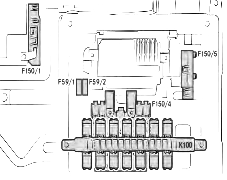
Power Fuse-Links and Relay Unit
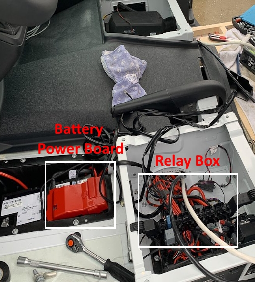
A power fusible link board is located on the plus terminal of the battery.
| Diagram | ||
|---|---|---|
|
||
| No. | Description | Amps |
| F150/1 board (MFB-1) | ||
| 1 | Battery charge sensor | - |
| 2 | Not assigned | - |
| 3 | Main fuse box (MFB-2) | - |
| 4 | Power Distribution Center Terminal 30 (F30-1 - F30-6) | 50 |
| 5 | Additional PTC heater | 125 |
| F150/4 board (MFB-2) | ||
| 1 | Terminal 30T, fuse box, driver's seat base (F55/1-F55/6) | 125 |
| 2 | Electrical control | 125 |
| 3 | Alternator | 300 |
| 4 | 400 | |
| 5 | Power Distribution Center (PDC), FB-P | 175 |
| 6 | Glow output stage (GZE) | 80 |
| 7 | radiator fan | 40/70/80 |
| 8 | Main fuses | 100 |
| 9 | empty | |
| 10 | Air conditioning in the rear | 25/50/100 |
| 11 | Additional battery / battery disconnect relay; | 100/150 |
| Retarder without additional battery. | ||
| 12 | Air Suspension (LFA) | 40 |
| 13 | Heated windshield | 80 |
| Board F150/5 (MFB-ZB) | ||
| 1 | Retarder | 100 |
| 2 | Hydroboard / tipper (preparation) | 250 |
| 3 | additional battery | |
| 4 | Battery disconnect relay | 150 |
| 5 | Socket, converter | 60 |
| 6 | Additional heating | 25 |
| Board F59/1 and F59/2 | ||
| 1 | Heated windshield | 40 |
| 2 | Heated windshield right | 40 |
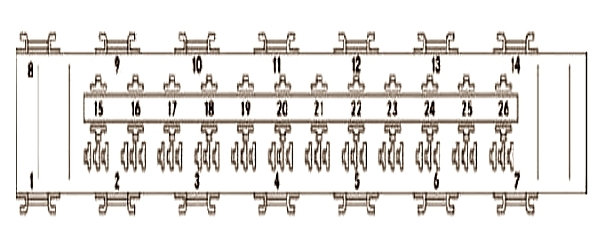
The relay box is located under the driver's seat.
| Relay box diagram | |
|---|---|
|
|
| No. | Purpose |
| 1 | Heated windshield |
| 2 | Terminal 15 |
| 3 | Rear window heating |
| 4 | 12V Outlets, rear |
| 5 | Interior lighting |
| 6 | Reserve |
| 7 | Reserve |
| 8 | Reserve |
| 9 | Reserve |
| 10 | Reserve |
| 11 | Reserve |
| 12 | Reserve |
| 13 | Reserve |
| 14 | Reserve |
| — | mini relay |
| 15 | Right rear wiper |
| 16 | Manufacturer's terminal block housing |
| 17 | Switch, reverse control signal |
| 18 | roof fan |
| 19 | Additional oil pump |
| 20 | Electric footrest right 1/2 |
| 21 | |
| 22 | Electric footrest left 1/2 |
| 23 | |
| 24 | Horn (beep) |
| 25 | Flashing beacon with siren |
| 26 | Loading elevator |

Hello,
I'm looking for the location of the fuses for the stop lights .
Thank-you for your help.
Regards.
I am looking for the stop light fuse in my 2019 3500 Mercedes sprinter. thank you.
2023 Sprinter 2500 relays are not in the right footwell. That is occupied by the jack tools. Sigh.
They are underneath the tool holder.