The third generation Mercedes-Benz Vito premiered at the Paris Motor Show in October 2014. It differs from its premium relative Viano by its simpler performance and affordable price. During the production period, the model has gone through one restyling. In this article, we will take a detailed look at the fuse box diagrams for the Mercedes Vito and Viano W447 (3rd generation) 2014, 2015, 2016, 2016, 2017, 2018, 2018, 2019, 2019, 2020, 2021, 2021, 2022, 2023 years of manufacture.

Here you will find the locations and photos of distribution boxes. The fuses responsible for the “Cigarette lighter” and “Fuel Pump” are highlighted in bold.
In the engine compartment
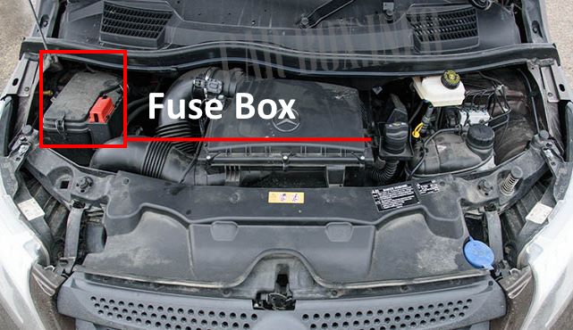
It is located on the right side of the underhood. The protective cover must be removed for access.
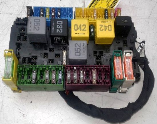
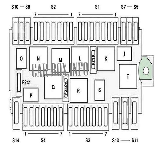
General view of the Mercedes Vito / Viano underhood fuse box.
| Diagram | ||
|---|---|---|
|
||
| No. | Description | A |
| Relay modules | ||
| J | Horn (beep) relay | |
| K | Continuous operation of the windshield wiper | |
| L | Wiper on/off | |
| M | Starter | |
| N | Terminal 87 | |
| O | Spare | |
| P | Spare | |
| Q | Spare | |
| R | Terminal 15 | |
| S | Spare | |
| T | Spare | |
| S1 board | ||
| 1 | ESP valves | 25 |
| 2 | Horn (beep) | 15 |
| 3 | The engine control unit | 5 |
| 4 | Automatic transmission control unit | 25 |
| 5 | Spare | - |
| 6 | Spare | - |
| 7 | Spare | - |
| S2 board | ||
| 1 | Spare | - |
| 2 | Terminal 87 (4) | 15 |
| 3 | Terminal 87 (2) | 15 |
| 4 | Terminal 87 (3) | 10 |
| 5 | Terminal 87 (1) | 20 |
| 6 | The engine control unit | 5 |
| 7 | Spare | - |
| S3 board | ||
| 1 | Headlight angle adjustment system, left-hand side | 5 |
| 2 | ESP system | 5 |
| 3 | Headlight angle adjustment system, right-hand side | 5 |
| 4 | Spare | - |
| 5 | Fuel filter heating system | 25 |
| 6 | Spare | - |
| 7 | Spare | - |
| S4 board | ||
| 1 | Spare | - |
| 2 | Spare | - |
| 3 | COLLISION PREVENTION ASSIST / DISTRONIC PLUS | 7.5 |
| 4 | Spare | - |
| 5 | Engine Radiator Fan / Radiator Shutters | 5 |
| 6 | Automatic transmission control unit | 10 |
| 7 | Additional oil pump (ZOP) | 15 |
| S5-S14 board | ||
| S5 | EDW system (anti-theft alarm system) buzzer | 5 |
| S6 | Independent heating system control unit | 20 |
| S7 | HLI LED headlight control unit (vehicle headlight functions) | 20 |
| S8 | ESP system control unit | 5 |
| S9 | Spare | - |
| S10 | Spare | - |
| S11 | Spare | - |
| S12 | ESP system pump | 40 |
| S13 | CBC signal registration and excitation module 2 | 40 |
| S14 | LED headlight control unit LCU (LED headlight) | 30 |
| Separate fuses | ||
| F239 | Windshield wipers front | 30 |
| F240 | Starter, terminal 50 | 25 |
| F241 | Spare | - |
In the cabin
There are three distribution boxes here, which are responsible for protecting the vehicle's electrical circuits.
Fuse box #1
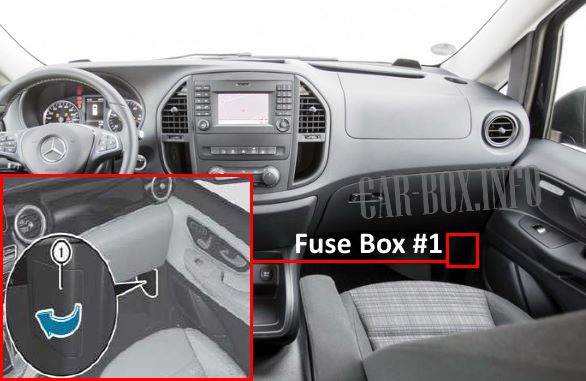
Located behind the protective cover on the pillar in the front passenger footwell.
| Diagram | ||
|---|---|---|

|
||
| No. | Description | A |
| S1 board | ||
| 1 | Rear seat heating system / rear seat ventilation system, 1st row left | 10 |
| 2 | Rear seat heating system / rear seat ventilation system, 1st row right | 10 |
| 3 | Rear seat heating system / rear seat ventilation system, 2nd row from left | 10 |
| 4 | Rear seat heating system / rear seat ventilation system, 2nd row right | 10 |
| 5 | Spare | - |
| 6 | Rear seat heating system / rear seat ventilation system control unit | 5 |
| S2 board | ||
| 1 | Parameterizable special module (PSM) | 25 |
| 2 | Parameterizable special module (PSM) | 25 |
| 3 | Spare | - |
| 4 | Spare | - |
| 5 | Electric sliding door, right / tailgate EASY-PACK | 30 |
| 6 | Spare | - |
| S3-S6 board | ||
| S3 | Marco Polo charger, charging connection | 25 |
| S4 | Terminal 30, bodybuilder | 25 |
| S5 | Spare | |
| S6 | Additional air heating | 25 |
| S10 board | ||
| 1 | Tachograph | 5 |
| 2 | Spare | - |
| 3 | Tachograph | 7.5 |
| 4 | Spare | - |
| 5 | Terminal 61, bodywork | 15 |
| Only for bodybuilder Westfalia | 5 | |
| 6 | Terminal 15, bodybuilder | 15 |
| Only for bodybuilder Westfalia | 5 | |
| 7 | Additional air heating timer | 5 |
| Relay modules | ||
| A | Terminal 15 relay | |
| B | Spare | |
| C | Spare | |
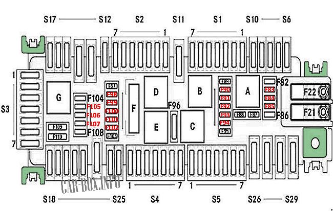
Fuse box #2
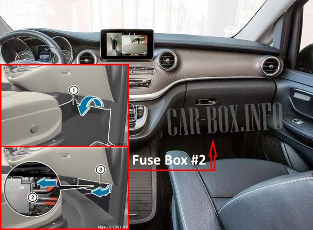
It is located behind the trim in the front passenger's footwell. To access it, pull out the floor trim (1). Then, press the bracket (2) and push the cover (3) in the direction of the arrow.
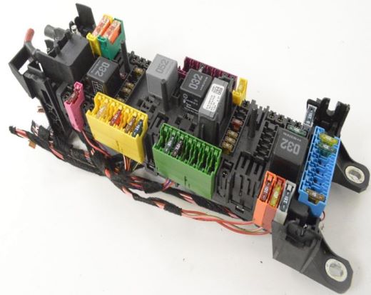
General view.
| Diagram | ||
|---|---|---|
|
||
| No. | Description | A |
| S1 board | ||
| 1 | Spare | - |
| 2 | Head module (radio receiver) | 25 |
| Mounting socket for retrofitting with radio receiver | 15 | |
| 3 | Lane keeping system, steering wheel | 10 |
| 4 | Heating system / air conditioning system "TEMPMATIK" / automated air conditioning system "TERMOTRONIK" | 10 |
| 5 | Control panel in the middle of the center console with touch panel | 7.5 |
| 6 | Head module, radio receiver (Vito) | 5 |
| Head module, radio receiver (V-Class) | 15 | |
| 7 | Mercedes Vito / Viano cigarette lighter fuse | 15 |
| S2 board | ||
| 1 | Driver's seat control unit | 7.5 |
| 2 | Fuse box in the engine compartment (PDC-E) | 30 |
| 3 | Airbag control unit | 7.5 |
| 4 | DAB/SDARS digital radio / TV tuner for Japan | 5 |
| 5 | Spare | - |
| 6 | Spare | - |
| 7 | Front passenger seat control unit | 7.5 |
| S3 board | ||
| 1 | Steering column tube module | 5 |
| 2 | Display and head module (radio) fan | 7.5 |
| 3 | Phone Receiver | 5 |
| 4 | Media Interface | 5 |
| 5 | Japan Toll User Registration System (DSRC) | 7.5 |
| 6 | Air conditioning fan | 30 |
| 7 | Ignition switch / electronic steering lock | 20 |
| S4 board | ||
| 1 | Front left door control unit | 30 |
| 2 | Front right door control unit | 30 |
| 3 | Rear window wiper, rear right door (Vito) | 20 |
| 4 | Electric Parking Brake (EFS) | 7.5 |
| 5 | Airbag control unit | 7.5 |
| 6 | Front passenger airbag automatic deactivation system | 5 |
| 7 | Spare | - |
| S5 board | ||
| 1 | Spare | - |
| 2 | 12 V sockets in cargo area | 15 |
| 3 | Electric Parking Brake (EFS) | 30 |
| 4 | Electric sliding door, left | 30 |
| 5 | Trailer module 1 | 15 |
| 6 | Trailer module 2 | 25 |
| 7 | Trailer module 3 | 25 |
| Board S6-S29 | ||
| S6 | Spare | - |
| S7 | trailer control unit | 7.5 |
| S8 | Support battery, charging connection | 10 |
| S9 | trailer control unit | 15 |
| S10 | A-pillar footwell fuse box (PDC-F) | 5 |
| S11 | Rear window heating system | 30 |
| S12 | Rear Passenger Entertainment System | 10 |
| S13 | Seat Belt Pretensioner, Front Left (PRE-SAFE®) | 40 |
| S14 | Right front seat belt pretensioner (PRE-SAFE®) | 40 |
| S15 | Exhaust gas neutralization system, SCR 3 | 10 |
| S16 | Exhaust gas neutralization system, SCR 2 | 20 |
| S17 | Exhaust gas neutralization system, SCR 1 | 15 |
| S18 | Exhaust gas neutralization system - SCR relay | 15 |
| S19 | Spare | - |
| S20 | Spare | - |
| S21 | Front passenger seat control unit | 30 |
| S22 | Driver's seat control unit | 30 |
| S23 | Amplifier, speaker system | 40 |
| S24 | Ceiling direction indicators | 10 |
| S25 | Fuel system control unit | 20 |
| S26 | Panoramic roof | 30 |
| S27 | Signal recording and excitation module CBC 1 | 40 |
| S28 | Signal recording and excitation module CBC 3 | 40 |
| S29 | Air conditioning fan in the rear of the car | 30 |
| Separate fuses on the relay holder | ||
| F21 | Additional heating device (PTC) | 200 |
| F22 | Support battery | 200 |
| F82 | Central gateway "Star 2" | 5 |
| F83 | Ignition lock | 7.5 |
| F84 | Control panel on the center console / control panel on the left near the steering wheel | 7.5 |
| F85 | Radio remote control, receiver / KOM module | 5 |
| F86 | Radio frequency antenna (RF antenna) | 5 |
| F87 | Diagnostic connector | 10 |
| F88 | instrument cluster | 10 |
| F89 | light switch | 5 |
| F90 | Lane change signaling | 5 |
| F90 | Exhaust gas neutralization system, SCR control unit | 5 |
| F92 | Fuel system control unit | 5 |
| F93 | Mounting socket for radio receiver retrofit | 7.5 |
| Japan Toll User Registration System (DSRC) | ||
| F94 | Spare | |
| F95 | Glove box lighting | 5 |
| F96 | Cargo door wiper / rear window wiper on left rear door (Vito) | 15 |
| F97 | PARKTRONIC / Active Parking Assist | 5 |
| F98 | Signal recording and excitation module, CBC system control line | 5 |
| F99 | Tire pressure monitoring system | 5 |
| F100 | Amplifier, speaker system | 5 |
| F101 | Roof control panel | 10 |
| F102 | Spare | - |
| F103 | Mounting socket for retrofitting with taxi equipment, taximeter | 5 |
| F104 | Rear passenger entertainment system, display, left side | 5 |
| F105 | Rear passenger entertainment system, display, right side | 5 |
| F106 | Driver assistance systems video camera | 5 |
| F107 | Mounting socket for retrofitting a TV/traffic camera | 5 |
| F108 | Reversing camera / 360° camera | 7.5 |
| F109 | Spare | - |
| F110 | Signal recording and excitation module, CBC 5 | 30 |
| Relay modules | ||
| A | Terminal 15 relay | |
| B | Rear window wiper | |
| C | Terminal 15 R2 | |
| D | Rear window heating system | |
| E | Terminal 15 R1 | |
| F | Terminal 30G | |
| G | Exhaust gas neutralization system, SCR system fuel supply pump | |
Power fusible links
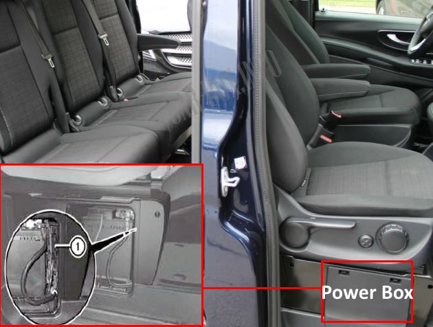
Located on the side of the passenger seat behind a protective cover.
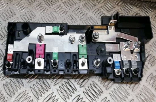
General view.
| Diagram | ||
|---|---|---|
|
||
| No. | Purpose | A |
| 1 | A16 - Spare | - |
| 2 | A15 - Spare | - |
| 3 | A1 - Starter | - |
| 4 | A8 - A-pillar footwell fuse box (PDC-F) | 150 |
| 5 | A15 - Additional battery | 150 |
| 6 | A2 - Preheating control unit | 100 |
| 7 | E2 - Alternator | 350 |
| 8 | Engine radiator fan - A10 | 100 |
| 9 | Spare | - |
| 10 | Fuse box in the engine compartment (PDC-E) - A7 | 150 |
| 11 | Spare | - |
| 12 | Spare | - |
| 13 | Fuse box in passenger footwell (PDC-P) - A6 | 250 |
| 14 | CBC signal registration and excitation module - A13 | 40 |
| 15 | Spare | - |
| 16 | A11 - Power steering | 100 |
| 17 | A4 - Power socket at the rear of the vehicle | 50 |
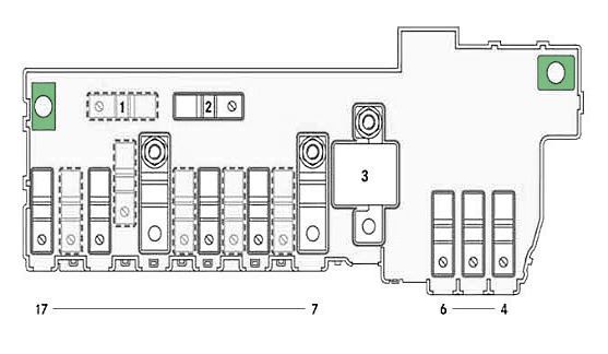
In the luggage compartment
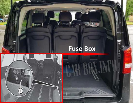
Located on the right side of the luggage compartment, behind the protective cover.
| Diagram | ||
|---|---|---|

|
||
| No. | Decryption | Amps |
| 1 | 12V power connector, 1st row of seats, left-hand side | 15 |
| 2 | 12V power connector, 2nd row of seats, left-hand side | 15 |
| 3 | 12V power connector, 2nd row of seats, right-hand side | 15 |
| 4 | Relay K127 - 12V power connector at the rear of the vehicle | |
