Mercedes-Benz W638 is the first generation of commercial minivans / minibuses of the Vito series of the German automobile manufacturer Daimler AG. It replaced the MB100 series vehicles. The car was put into serial production in 1995. In this article, we will take a detailed look at the fuse box diagrams for the Mercedes Vito W638 (1st Gen) 1996, 1997, 1998, 1999, 2000, 2001, 2002, 2003 year of manufacture.
Here you will find the locations and photos of distribution boxes. The fuses responsible for the “Cigarette lighter” and “Fuel Pump” are highlighted in bold.
In the passenger compartment
There are two distribution boxes here that are responsible for protecting the electrical circuits.
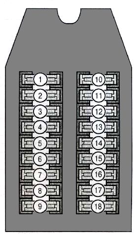
Unit #1
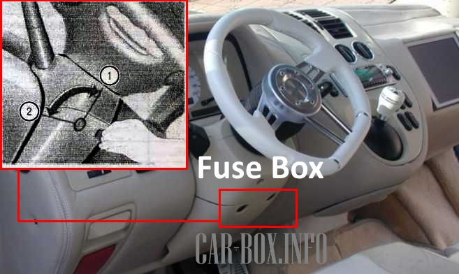
Fuse box on the underside of the steering column 1. Closed 2. Open.
The photo shows an example.
| Diagram | ||
|---|---|---|
|
||
| No. | A | Description |
| 1 | 15 | Parking light, right rear position lamp |
| 2 | 15 | High beam headlight, right |
| 3 | 15 | Left high beam headlamp, high beam indicator light |
| 4 | 15 | Reverse light, buzzer, central locking system |
| 5 | 15 | Stop lamps |
| 6 | 20 | Front and rear wipers, emergency alarm system |
| 7 | 15 | Power circuit 15 |
| 8 | 20 | Interior lighting, Vito cigarette lighter fuse, radio (power circuit 30) |
| 9 | 15 | Turn indicators, instrument cluster, tachograph |
| 10 | 15 | Instrument cluster illumination, license plate illumination, daytime running light |
| 11 | 15 | Parking light, left rear position light |
| 12 | 15 | Right dipped beam headlight, rear fog light |
| 13 | 15 | Left dipped beam headlamp |
| 14 | 15 | Fog headlight |
| 15 | 15 | Radio (15 R power circuit), airbag control |
| 16-18 | - | Not used |
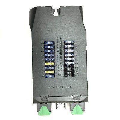
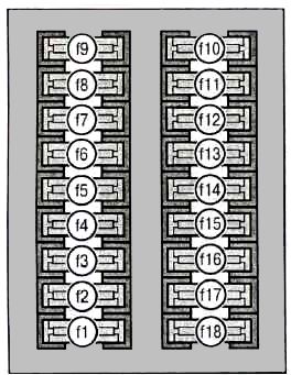
Unit #2
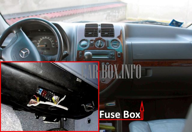
The second fuse box is located in the front passenger footwell under the glove box.
| Diagram | ||
|---|---|---|
|
||
| No. | A | Appointment |
| f1 | 7.5 | Swivel glass |
| f2 | 30 | Passenger door window handle, front sliding sunroof |
| f3 | 30 | Driver's door window handle, rear sliding sunroof |
| f4 | 25 | Central locking device, Komfortschliessanlage regulator |
| f5 | 10 | Interior lighting, front passenger mirror illumination |
| f6 | 20 | 12V Plug sockets |
| f7 | 7.5 | Phone network D, mobile phone |
| f8 | 20 | Anti-theft alarm control unit (EDW), EDW alarm switch |
| f9 | 10 | Auxiliary heater relay |
| f10 | 7.5 | Anti-theft warning horn (EDW) |
| f11 | 7.5 | Left anti-theft system flashing light (EDW) |
| f12 | 15 | Right anti-theft system flashing light (EDW) |
| f13 | 7.5 | EDW 2 system |
| f14 | 7.5 | EDW system 2, anti-theft alarm horn |
| f15 | 7.5 | IRS Sensors EDW2 |
| f16-f18 | - | Not |
Unit #3
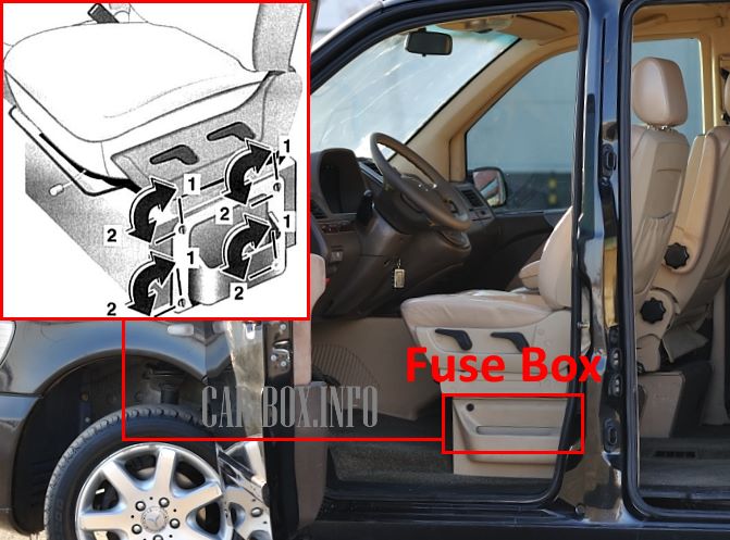
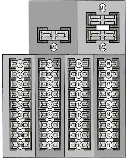
Third fuse box under the driver's seat: location.
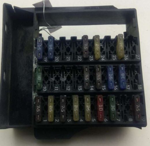
General view.
| Diagram | ||
|---|---|---|
|
||
| No. | A | Decryption |
| f1 | 7.5 | Electronic control unit ABS, ASR, EBV (depending on equipment), air suspension control unit |
| f2 | 25 | Combined rear wiper relay |
| f3 | 7.5 | Immobilizer control unit |
| f4 | 25 | Radiator fan (gasoline engine), charge air cooler (diesel engine) |
| f5 | 25 | Hydraulic unit (valves) |
| f6 | 10 | Immobilizer, automatic transmission control unit |
| f7 | 30 | Heater fan |
| f8 | 20 | Headlight washer relay |
| f9 | 7.5 | Additional heater control unit |
| f10 | 25 | Trailer, refrigerator socket |
| f11 | 30 | Combined rear wiper relay, anti-towing device (EDW / ZV) |
| f12 | 10 | Heating control unit (Heizmatik) |
| f13 | 30 | Air suspension compressor relay |
| f14 | 7.5 | Air suspension control unit, tachograph, auxiliary light |
| f15 | 7.5 | Radio power supply |
| f16 | 15 | Heating control unit, cab console |
| f17 | 15 | Automatic transmission gear selector |
| f18 | 10 | Telephone, mobile phone, anti-theft control unit, heated door mirrors |
| f19 | 15 | Supply circuit 15 (gasoline engine), crankcase ventilation heater (diesel engine) |
| f20 | 15 | Terminal 15 (gasoline engines) |
| f21 | 15 | Ignition coil power supply (gasoline engine) |
| f22 | 20 | Fuel module - Mercedes Vito fuel pump fuse (gasoline engine) |
| f23 | 7.5 | Diesel engine control unit |
| f24 | 25 | |
| f25 | 10 | Auxiliary heater relay |
| f26 | 25 | Heater control unit (diesel engine), power supply for non-volatile heater (operation with engine stopped) |
| f27 | 25 | Additional heater control unit |
| f28 | 15 | Relay circuit D +, daytime running light relay K89 |
| f29 | 10 | Relay daytime running light K69 |
| f30 | 10 | Relay daytime running light K68 |
| f31 | 10 | Power circuit relay 58 |
| f32 | 30 | Left seat heating and position adjustment circuit |
| f33 | 25 | Right seat heating and position adjustment circuit |
| f34 | 7.5 | Water separator |
| f35 | 7.5 | Rear air conditioner |
| f36 | 15 | |
| M1 | 40 | Engine cooling fan assembly 250 W |
| - | 60 | Engine cooling fan unit 500 W |
| M3 | 40 | Secondary air blower (gasoline engine) |
| Relay box under the driver's seat | |
|---|---|
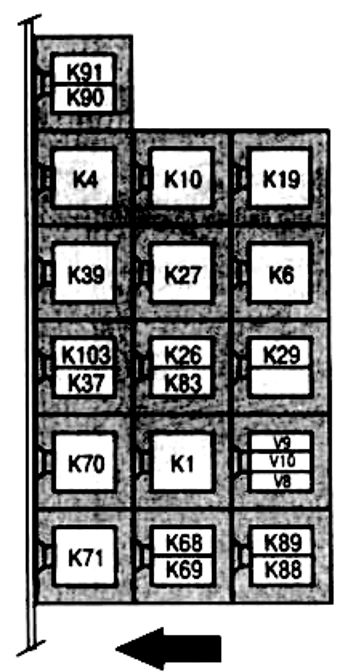
|
|
| No. | Appointment |
| K91 | Right side turn signal relay (central locking system with remote control) |
| K90 | Left turn signal relay (central locking system with remote control) |
| K4 | Power circuit relay 15 (steering column lock 2) |
| K10 | Air Suspension Compressor Relay |
| K19 | Block headlamp window cleaning relay |
| K39 | fuel module (fuel pump relay) |
| K27 | Passenger detection relay (Seat unloaded relay) |
| K6 | the engine control unit |
| K103 | Engine cooling booster pump relay |
| K37 | Horn (beep) relay |
| K26 | supply circuit D (steering column lock 3) |
| K83 | fog lamps |
| K29 | Stationary heater relay (ZHE) |
| K70 | supply circuits 15 (special equipment) |
| K1 | starter lock |
| V9 | Anti-theft system diode ATA 1 |
| V10 | Anti-theft system diode ATA 2 |
| V8 | Stationary heater booster pump diode |
| K71 | power circuit 58 |
| K68 | DRL system |
| K69 | |
| K88 | Fog Lamp Relay 1 (with DRL System) |
| K89 | Fog Lamp Relay 2 (with DRL System) |
