The Mercedes-Benz Vito (W639) is an all- or rear-wheel drive minivan with three length options (4763 mm; 5008 mm, 5238 mm), two wheelbase options (3200 mm; 3430 mm) and a choice of four modern gasoline and diesel engines with six-speed manual or five-speed TouchShift automatic transmission. In this article, we will take a detailed look at the fuse box diagrams for the Mercedes Vito W639 (2nd generation) 2003, 2004, 2005, 2006, 2007, 2008, 2009, 2010 years of manufacture.

Here you will find the locations and photos of distribution boxes. The fuses responsible for the “Cigarette lighter” and “Fuel Pump” are highlighted in bold.
In the passenger compartment
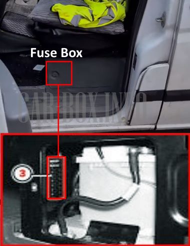
The distribution box is located under the driver's seat.
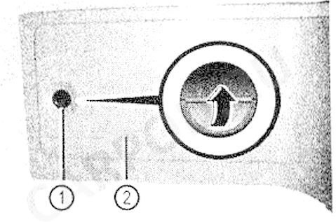
You have to turn the lock to access it.
And remove the protective cover.
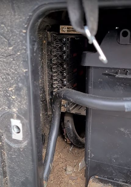
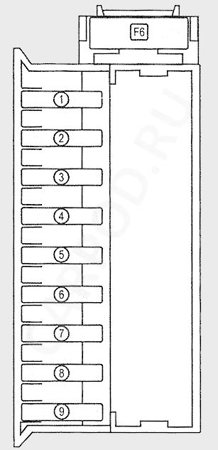
| Schematic diagram of the cabin unit | ||
|---|---|---|
|
||
| No. | A | Consumer |
| 1 | 25 | Control panel on the left door |
| 2 | 25 | Control panel on the right door |
| 3 | 25 | PSM control unit |
| 4 | 25 | |
| 5 | 15 | 12V socket in the compartment under the passenger seat |
| 6 | Empty | |
| 7 | 7.5 | Parking heater timer and illumination |
| 9 | 25 | Parking heater |
| 9 | 25 | |
| F6 | 80 | SAM-SRB |
In the engine compartment
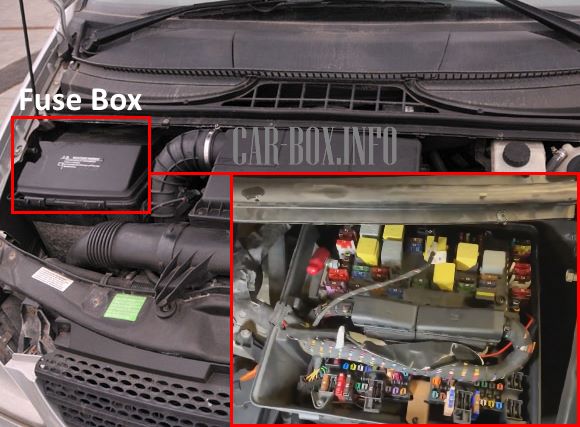
Located on the right side of the engine compartment.
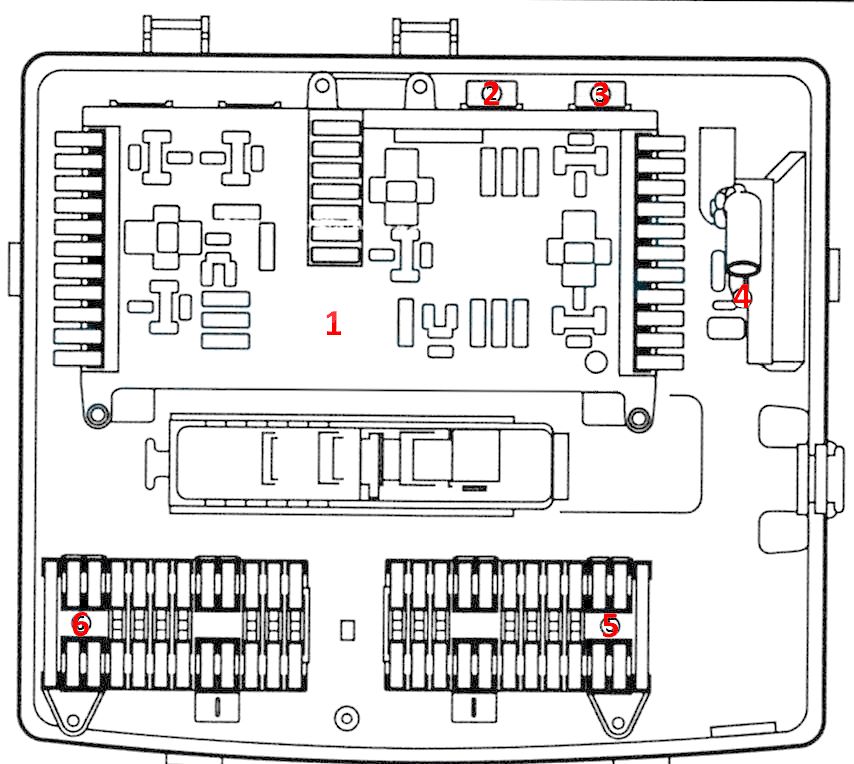
Layout of elements in the block:
№1. Main panel,
№2. Socket F4,
№3. Socket F5,
№4. Trunk fuse F1,
№5. Panel F34,
№6. Panel F35
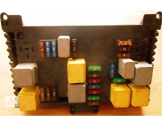
Photo - an example of the execution of the main board.
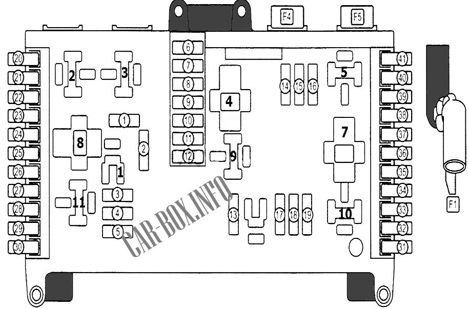
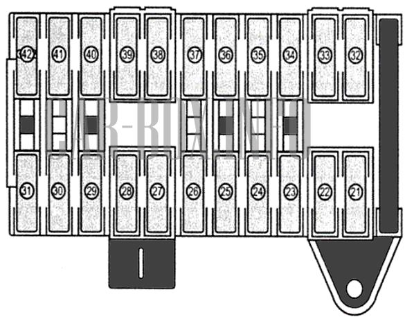
| Main board diagram (#1 in the picture) | ||
|---|---|---|
|
||
| No. | A | Description |
| 1 | 30 | Front wiper |
| 2 | 15 | Horn (beep) |
| 3 | 5 | Stop signal switch |
| 4 | 7.5 | Heater |
| 5 | Diagnostic unit | |
| 6 | 5 | Automotive components |
| 7 | 30 | Rear wiper |
| 8 | 10 | Circuit. 87 (1) |
| 9 | 15 | Circuit. 87 (2) |
| 10 | 10 | Circuit. 87 (3) |
| 11 | 7.5 | Circuit. 30 2 electric motor |
| 12 | 30 | Rear window heating |
| 13 | 7.5 | Ignition switch lock and anti-theft system |
| 14 | 7.5 | Brake system |
| 15 | 5 | Headlight beam angle adjuster |
| 16 | 25 | Starter |
| 17 | 15 | Fuel module (fuel pump fuse) |
| 18 | 15 | Vito cigarette lighter fuse |
| 19 | 5 | Radio |
| 20 | 15 | Ignition system (petrol engine) |
| 21 | 7.5 | Power supply for automatic transmission control system |
| 22 | 7.5 | Tachograph |
| 23 | 10 | Airbag control unit |
| 24 | Not used | |
| 25 | 5 | Trailer control unit |
| 26 | 5 | Isolating Relay |
| 27 | 5 | Circuit. 15 |
| 28 | 10 | Drive control device |
| 29 | Not | |
| 30 | ||
| 31 | 10 | Buzzer for EDW system |
| 32 | 5 | VICS mobile phone connection |
| 33 | 10 | Airbag, AKSE system |
| 34 | 5 | Circuit. 15 |
| 35 | 7.5 | Sliding roof control and drive unit |
| 36 | 10 | Power seat position adjustment |
| 37 | 7.5 | Passenger mirror light |
| 38 | 7.5 | Inner part of the body behind the front seats |
| 39 | Not | |
| 40 | 10 | CDI system control unit |
| 41 | 10 | |
| F 1 | 150 | Circuit 30 on-board mains, alternator |
| F4 | 60 | Air conditioner fan |
| F5 | 40 | Secondary fan |
| No. | Relays | |
| 1 | Horn (beep) relay | |
| 2 | 1/2 windshield washer motor | |
| 3 | ||
| 4 | Engine management system | |
| 5 | Starter | |
| 6 | Gasoline module (Mercedes Vito w639 fuel pump relay) | |
| 7 | Main ignition circuits | |
| 8 | ||
| 9 | Rear window heating | |
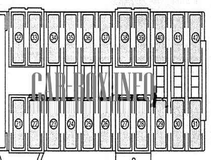
| Additional F34 block diagram (#5 in the picture) | ||
|---|---|---|
|
||
| No. | A | Decryption |
| 21 | 5 | Center light switch and overhead control panel |
| 22 | 7.5 | Consumers in the rear of the passenger compartment |
| 23 | 10 | Lighting plafond |
| 24 | 7.5 / 25 | Sliding roof (sunroof) drive |
| 25 | 25 | Panoramic sliding roof drive |
| 26 | 5 | Radio |
| 27 | 7.5 | Air conditioning, Rear cabin consumers |
| 28 | 15 | Rear cabin consumers |
| 29 | 7.5 | Mobile phone / LINGUATRONIC system |
| 30 | 30 | Heated seats |
| 31 | 5 | Tachograph |
| 32 | Not | |
| 33 | 10 | Diagnostic unit |
| 34 | Not | |
| 35 | 5 | Tempmatik system / air conditioner |
| 36 | 30 | Headlight washer |
| 37 | 10 | Buzzer EDW |
| 38 | 20 | Locking the steering columns |
| 39 | 40 | Fan |
| 40 | 25 | ABS control unit |
| 41 | 40 | |
| 42 | 15 | Radio / COMAND system |
| Board #F35 diagram (#6 in the picture) | ||
|---|---|---|
|
||
| No. | A | Description |
| 21 | 15 | 12 V consumer power supply to the left center cabin pillar |
| 22 | 15 | 12 V consumer power supply on the left center pillar of the passenger compartment |
| 23 | 30 | Trailer electrical connector |
| 24 | 25 | Trailer identification device |
| 25 | 30 | Adjusting the driver's seat position |
| 26 | 30 | Adjusting the passenger's seat position |
| 27 | 30 | Electric actuator of the left sliding door |
| 28 | 30 | Electric actuator of the right sliding door |
| 29 | 30 | Fan |
| 30 | 40 | Air suspension power supply |
| 31 | 10 | Parktronic |
| 32 | 5 | Tire pressure monitoring system |
| 33 | Not | |
| 34 | 5 | Mobile phone / TV amplifier |
| 35 | 20 | Parking heater control unit |
| 36 | Not | |
| 37 | 5 | Air conditioner |
| 38 | Not | |
| 39 | ||
| 40 | 15 | 12 V outlet |
| 41 | 10 | Control unit for additional direction indicators on the roof |
