
Table of Contents
The Nissan Murano is a mid-size crossover SUV.
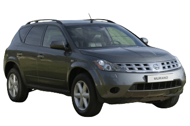
First-generation models (chassis codes Z50, TZ50, PZ50, PNZ50; FF-L platform) were produced from 2002 through 2007.
Passenger Compartment Fuse Box
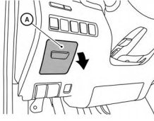
Located on the driver's side (left) of the instrument panel.
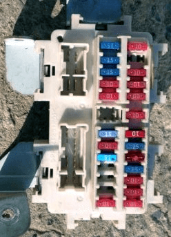
Fuse Box Overview
| Diagram | |
|---|---|
|
|
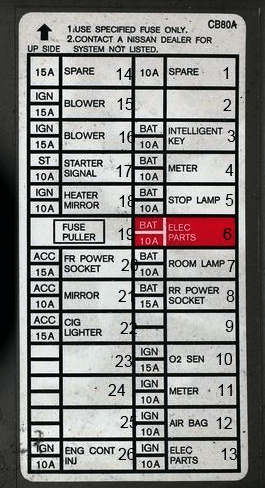
| No. | Description |
| 1 | 10A – Spare |
| 2 | Empty |
| 3 | 10A – Intelligent Key System |
| 4 | 10A – Instrument Cluster |
| 5 | 15A – Stop Lamps |
| 6 | 10A – Body Electrical Equipment |
| 7 | 10A – Interior Lighting |
| 8 | 15A – Rear Auxiliary Power Outlet |
| 9 | Empty |
| 10 | 15A – Heated Oxygen Sensor (HO2S) |
| 11 | 10A – Instrument Cluster |
| 12 | 10A – Supplemental Restraint System (Airbags) |
| 13 | 10A – Electronic Control Modules |
| 14 | 15A – Spare |
| 15 | 10A – HVAC Blower Fan |
| 16 | 10A – HVAC Blower Fan |
| 17 | 10A – Starter Signal |
| 18 | 10A – Heated Door Mirrors |
| 19 | Empty |
| 20 | 15A – Front Auxiliary Power Outlet |
| 21 | 10A – Power Outside Mirrors |
| 22 | 15A – Cigarette Lighter |
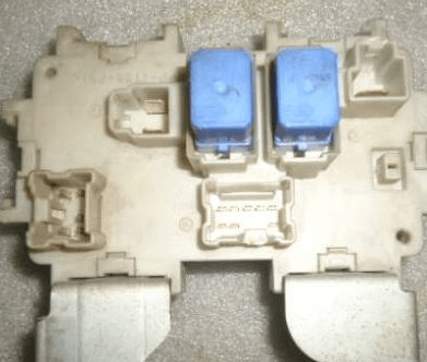
An auxiliary bracket adjacent to the panel houses the blower motor relay and the ignition auxiliary relay. |
|
Engine Compartment Fuse Boxes
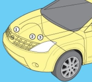
The fuse and relay boxes are located in three separate positions within the engine compartment.
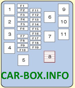
Main Engine Bay Fuse & Relay Box
Located on the right-hand (passenger-side) frame rail.
| Diagram & Photo | |
|---|---|

|
|
|
|
| No. | Description |
| 1 | Engine Control Module (ECM) Relay |
| 2 | Headlamp High-Beam Relay |
| 3 | Headlamp Low-Beam Relay |
| 4 | Starter Relay |
| 5 | Ignition Main Relay |
| 6 | Empty |
| 7 | Empty |
| 8 | Empty |
| 9 | Electronic Throttle Control (ETC) Relay |
| 10 | Fuel Pump Relay |
| 11 | Front Fog Lamp Relay |
| F1 | (10A) Spare |
| F2 | (10A) Right Headlamp (High Beam) |
| F3 | (30A) Windshield Wiper Motor & Washer |
| F4 | (10A) Left Headlamp (High Beam) |
| F5 | (20A) Heated Rear Window (Defogger) |
| F6 | (15A) Right Headlamp (Low Beam) |
| F7 | (15A) Spare |
| F8 | (15A) Spare |
| F9 | (10A) Air Conditioning Compressor Clutch |
| F10 | (20A) Heated Rear Window (Defogger) |
| F11 | (15A) Fuel Pump |
| F12 | (10A) Spare |
| F13 | (10A) Transmission Control Module (TCM) |
| F14 | (10A) Spare |
| F15 | Empty |
| F16 | (15A) Left Headlamp (Low Beam) |
| F17 | (15A) Engine Control System (ECM) |
| F18 | (15A) Front Fog Lamps |
| F19 | Empty |
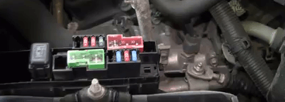
Battery Mounted Fuse Box
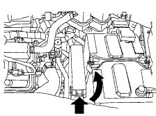
Location
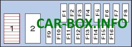
Fuse Box Overview
| Diagram | |
|---|---|
|
|
| No. | Description |
| 1 | Headlamp Washer Relay |
| 2 | Horn Relay |
| F1 | Empty |
| F2 | (10A) Horn |
| F3 | (10A) Alternator |
| F4 | (30A) Trailer Towing Harness |
| F5 | (50A) Spare |
| F6 | Empty |
| F7 | (30A) ABS / VDC Control Unit |
| F8 | (40A) Headlamp Washer Motor |
| F9 | (50A) ABS / VDC Actuator |
| F10 | (40A) Radiator Cooling Fan Motor 1 |
| F11 | (40A) Radiator Cooling Fan Motor 2 |
| F12 | (40A) Ignition Switch Circuits |
| F13 | (10A) Power Liftgate Opener |
| F14 | (15A) Heated Seats |
| F15 | (10A) All-Wheel Drive (AWD) Control Module |
| F16 | (15A) Spare |
Note: High-current fusible links are integrated directly onto the positive battery terminal.