The second generation Nissan Almera has the N16 body mark and was produced in 2000, 2001, 2002, 2003, 2004, 2005 and 2006 with hatchback and sedan bodies. The restyling of 2003 mainly affected the appearance of this car. In our publication you will find information describing the fuse blocks and relays nissan almera n16, their location and purpose.
Fuse boxes location

This vehicle has 3 main box with fuses and relays. One in the cabin and two in the engine compartment. See the diagram for details.
In the passenger compartment
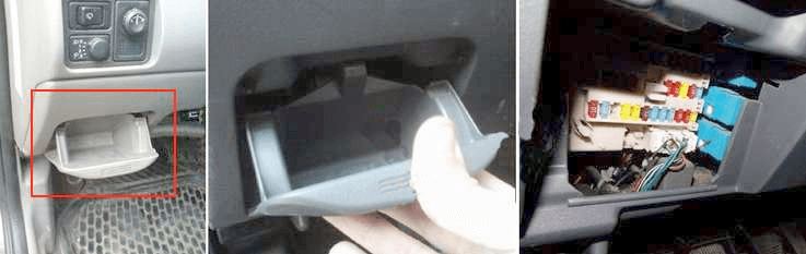
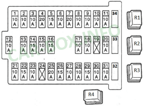
Fuse box located in the dashboard on the left side, behind the glove compartment.
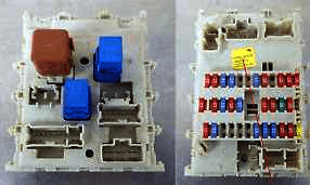
Photo - example.
| Diagram | |
|---|---|
|
|
| № | Description |
| 1 | 10A Power Mirrors |
| 2 | 10A Brake lights |
| 3 | 15A Power outlet |
| 4 | 7,5А For additional electrics |
| 5 | 15A Alarm and turn signals |
| 6 | 10A For additional electrics |
| 7 | 20A Heated rear window |
| 8 | 10A Oxygen sensor |
| 9 | 10A Additional power accessories |
| 10 | 10A Electrical package |
| 11 | 10A Automatic transmission controller |
| 12 | 10A ECU (i.e. all control of all turn signals, backlight and main power supply of the dashboard, panel backlight where the stove is) |
| 13 | 10A Interior lamp |
| 14 | 15A Interior blower motor (heater / air conditioner) |
| 15 | 10A Air conditioner |
| 16 | 15A Interior blower motor (heater / air conditioner |
| 17 | 10A Fuel injection system |
| 18 | 10A Airbags |
| 19 | 20A Additional power accessories |
| 20 | 10A Engine Controller |
| 21 | 10A Start signal |
| 22 | 15A Cigarette lighter |
| 23 | Spare |
| 24 | 20A Additional power accessories |
| 25 | 20A Windshield wiper |
| 26 | 7,5А For additional electrics |
| 27 | 15A Front and / or rear window washer (on the steering column switch) |
| 28 | 15A Rear window washer |
| 29 | 15A Fuels pump fuse |
| 30 | 10A Speedometer, tachometer, temperature and fuel gauges |
| 31 | 10A ABS |
| 32 | 10A Spare |
| 33 | 15A Spare |
| 34 | 20A Spare |
| R1 | Headlamp relay |
| R2 | Throttle valve control relay |
| R3 | Power window relay |
| R4 | R4 Rear fog lamp relay |
| Rear side relay | |

|
|
| R1 | Ignition relay |
| R2 | Blower motor relay |
| R3 | Relay for additional equipment (electrical accessories) |
In the engine compartment
Fuse box
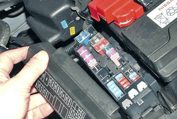
Located next to the battery. The lid will be marked with an up-to-date diagram with a description.
| Diagram |
|---|

|
| Legend |
| A 100A Generator (battery charging) |
| 40A power windows |
| With 40A cooling fan controller |
| D 40A regulator of cooling fans |
| E 30A for diesel engines |
| F 60A for diesel engines |
| G 80A for diesel engines |
| H 80A main power supply, ground circuit |
| I 50A ABS |
| J 30A to battery ignition switch |
| K 30A ABS / ESP |
| L 30A ESP |
| M 30A Headlight washer |
| 32 20A Rear window washer |
| 33 15A Fog lights |
| 34 15A Electric actuator and relay for electric throttle valve |
| 35 15A Headlights, daytime running lights |
| 36 15A Headlights, daytime running lights |
| 37 10A Rear fog lamp |
| 38 10A Tail lamps, license plate lighting |
| 39 10A Klaxon, battery charging (excitation current to the generator from the battery) |
| 40 15A Audio, navigation, LCD |
| 41 10A Engine management system |
| 42 10A Ignition coil |
| 43 10A USR |
| 44 20A Engine ECU |
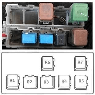
Relay panel
It is located at the right wing, on the side of the washer fluid barrel.
| Diagram | |
|---|---|
|
|
| № | Legend |
| R1 | 3rd relay radiator fan (25221E) |
| R2 | Front tumanki Fog lamps (25224QA) |
| R3 | Air conditioner relay E6 (25224D) |
| R4 | Horn relay (25620) |
| R5 | Radiator fan relay (25224J) |
| R6 | Headlights, light (25224A) |
| R7 | Starter (25224G) |
