Nissan Almera N15, the first generation car, at that time, of the Japanese company Nissan. Produced in 1995, 1996, 1997, 1998, 1999 and 2000. Mostly it was a three or five door hatchback. Restyling in 1998 mainly affected the exterior, bumper and side skirts. We propose to get acquainted with the location of all electronic control units nissan almera n15, fuse blocks and relays, as well as their diagrams and descriptions. The fuse responsible for the “Cigarette lighter” is highlighted in bold.

In the cabin
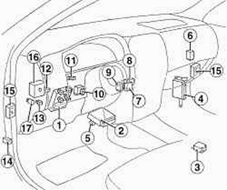
All electrical equipment in the passeneger compartment
|
|
| 1 | distribution box for fuses and relays; |
| 2 | electronic engine control unit; |
| 3 | airbag control unit; |
| 4 | ABS electronic control unit; |
| 5 | engine control unit relay; |
| 6 | windscreen wiper time relay; |
| 7 | centralized blocking unit for door locks; |
| 8 | starter blocking relay; |
| 9 | the control unit for the signaling device of non-switched off external lighting with a key in the ignition lock (instrument and starter switch); |
| 10 | relay-interrupter for direction indicators and alarm; |
| 11 | brake light switch; |
| 12 | fog lamp relay; |
| 13 | fuel pump relay; |
| 14 | rear window wiper time relay; |
| 15 | Door switch harness connector |
| 16 | connector for the wiring harness of the passenger compartment and engine compartment; |
| 17 | switch for power windows and sunroof. |
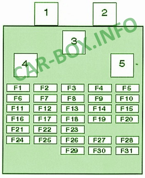
Fuse box

The photo.
| Diagram | |
|---|---|
|
|
| № | Legend |
| 1 | Sunroof motor relay (without power windows) |
| 2 | Heated mirror relay |
| 3 | Heater blower motor relay |
| 4 | Relay for main ignition circuits |
| 5 | Relay for auxiliary ignition circuits |
| F1 | (15A) Heater, air conditioner |
| F2 | (15A) Heater, air conditioner |
| F3 | (20A) Heated rear window (without daytime running light) |
| F4 | (15A) Front fog lamps |
| F5 | (20A) Heated rear window (with daytime running light) |
| F6 | (7.5A) Idle speed control valve - air conditioning, air conditioning shutdown system, heater, air conditioning |
| F7 | (7.5A) Diagnostic socket, power window relay, sunroof power relay, rear window defogger timer relay, immobilizer control unit |
| F8 | (10A) Automatic transmission control system, reversing lights, instrument cluster, indicators |
| F9 | (10A) Rear window wiper |
| F10 | (15A) Clock light, audio system |
| F11 | (7.5A) Direction indicators |
| F12 | (7.5A) ABS electronic control unit |
| F13 | (15A) Cigarette lighter fuse |
| F14 | (10A) Brake lights, ABS electronic control unit |
| F15 | (10A) Alarm |
| F16 | (10A) Heated oxygen sensor |
| F17 | (15A) Fuel pump, auxiliary air control valve |
| F18 | (10A) Heated seats |
| F19 | (20A) Windshield wiper |
| F20 | (7.5A) Interior lamps |
| F21 | (3A) SRS electronic control unit (single airbag system) |
| F22 | (10A) SRS control module (dual airbag system) |
| F23 | (10A) Heated door mirrors |
| F24 | (7.5A) Glow plug relay, headlight range control, clock, audio system, immobilizer control unit |
| F25 | (10A) E / m valve for cleaning the fuel vapor recovery system, e / m valve for cleaning the EGR system, idle speed control valve (IAC) -SOHC, e / m valve for variable valve timing, cooling fan motor relay, glow plug relay , advance control at partial load, e / m fuel cutoff valve, air conditioning, start inhibit relay - automatic transmission, daytime lighting control unit, rear window heater relay, ignition on signal to the electronic engine control unit (CD20E, diesel) |
| F26 | (7,5A) Start signal to electronic engine control unit - CD20E diesel, daytime lighting control unit |
| F27 | Spare |
| F28 | Spare |
| F29 | (15A) Headlamp cleaners |
| F30 | Spare |
| F31 | Spare |
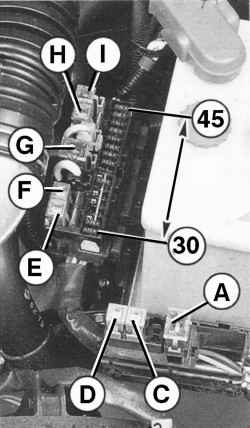
Under the hood
The engine compartment contains 3 fuse and relay boxes. Two on the left, next to the battery, and one on the right. The number of their elements may differ and depends on the vehicle configuration.
| Diagram (box next to the battery) |
|---|
|
| Description |
| A 75A System pre and post-heating |
| C 30A ABS solenoid valve control relay |
| D 30A Relay, hydraulic pump ABS |
| E 30A Electric fan of the engine cooling system. Climatic installation |
| F 25A Centralized door lock system. Electric sunroof |
| G 75A Onboard power supply |
| H 30A Electric fan of the engine cooling system. Climatic installation |
| I 30A Power supply circuit of the ignition switch or instrument and starter switch |
| 30 7.5A Electromagnetic clutch of the air conditioner compressor. Electro-pneumatic valve of accelerated idle speed 2 on |
| 31 7.5A Generator voltage regulator power supply circuit |
| 36 10A Headlights (side light). Rear lights (side light) |
| 37 - Reserve |
| 38 - Reserve |
| 39 15A Right headlight (low and high beam) |
| 40 15А Left headlight (low and high beam). High beam headlight control lamp |
| 41 7.5A Camshaft position and engine speed sensor. Mass air flow meter. Immobilizer |
| 42 10A Sound signal |
| 43 7.5A Rear lights (fog light) |
| 44 10A Rear lights (side light). License plate light |
| 45 10 Rear lights (side light) |
Block with relay
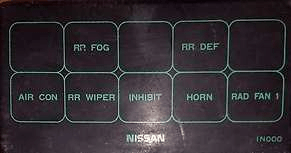
The current decoding is on the cover.
- Cooling Fan Motor Relay - Low Speed
- Horn relay
- Starter relay
- Relay for intermittent operation of the rear window wiper
- Air conditioner relay
- Cooling fan motor relay (high speed) SOHC - DKPP, DOHC, diesel
- Cooling fan motor relay 2 - DOHC, air conditioning, diesel
- Rear fog lamp relay
