
Most electrical circuits in this crossover are protected by fuses. High-current loads—such as headlights, cooling fan motors, and the fuel pump—are connected via relays. Fuses and relays are housed in power distribution boxes located in the engine compartment and the passenger compartment.
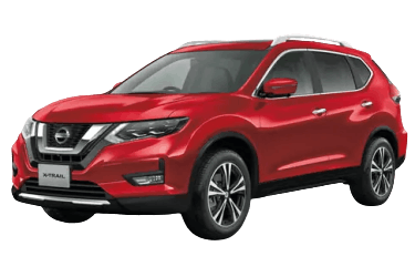
This article provides detailed fuse box diagrams and terminal assignments for the third-generation Nissan X-Trail (chassis code T32; CMF-CD platform), model years 2013 through 2019.
Passenger Compartment Fuse Boxes
The interior fuse panels are located at both ends of the instrument panel.
Main Fuse Box
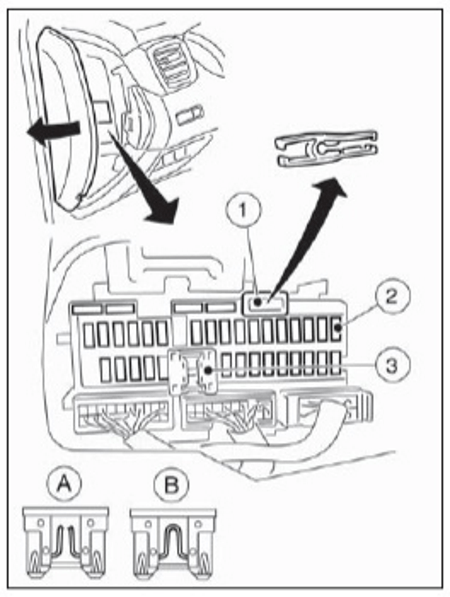
Location.
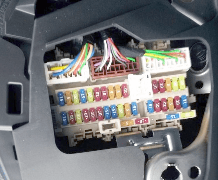
Fuse box layout (inverted view shown).
| Diagram | |
|---|---|
|
|
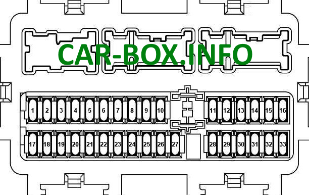
| No. | Circuit Protected / Legend |
| 1 | 15A Turn signals, hazard warning lights (Body Control Module [BCM]) |
| 2 | 5A All-Wheel Drive (AWD) control module |
| 3 | 20A Central door locking (Body Control Module [BCM]) |
| 4 | 15A Rear window wiper (Body Control Module [BCM]) |
| 5 | 20A Central door locking (Body Control Module [BCM]) |
| 6 | 10A All-Wheel Drive (AWD) control module, Data Link Connector (DLC), electric parking brake |
| 7 | 10A Body Control Module (BCM) |
| 8 | 5A Clutch pedal switch |
| 9 | 1A Nissan Anti-Theft System (NATS) antenna |
| 10 | 10A Stop lamp switch |
| 11 | 20A Audio system |
| 12 | 10A Subwoofer (auxiliary jack) |
| 13 | 10A Instrument cluster |
| 14 | 5A Body Control Module (BCM), security siren module |
| 15 | 20A Audio system, navigation control module, Around View Monitor (AVM) |
| 16 | 20A Audio system, navigation control module, Around View Monitor (AVM) |
| 17 | 15A Blower motor, HVAC system |
| 18 | 10A Spare fuse |
| 19 | 20A Cigarette lighter / 12V power outlet |
| 20 | 10A Climate control system, brake pedal switch, stop lamp switch (R9M engine), power mirror control unit |
| 21 | 10A ABS control module, Vehicle Dynamic Control (VDC) |
| 22 | 10A Heated outside mirrors |
| 23 | 15A Heated rear window |
| 24 | 15A Heated rear window |
| 25 | 20A Interior lighting relay (Body Control Module [BCM]), auxiliary connector |
| 26 | 5A Navigation control module, headlight leveling system, audio system |
| 27 | 15A Blower motor, HVAC bypass relay |
| 28 | 15A Heated front seats |
| 29 | 10A DC-DC converter |
| 30 | 10A Stop lamp switch, steering angle sensor, parking sonar module, ESP control module, AWD control module, Data Link Connector (DLC), audio system, navigation unit, Around View Monitor, electric parking brake, chassis control module, auto-dimming mirror, auxiliary connector, combination switch, fuel heater relay, radar distance sensor, front camera, PTC heater relays 1, 2, 3 |
| 31 | 5A Instrument cluster, diode |
| 32 | 10A Supplemental Restraint System (SRS) / Airbags |
| 33 | 15A Windshield washer pump, combination switch |
Fuse No. 19 (20A) protects the cigarette lighter circuit. Individual relays are located on the reverse side of the panel: Ignition, Blower Motor, Rear Defogger, and Auxiliary Relay.
Auxiliary Fuse Box
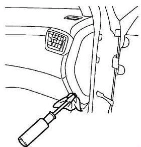
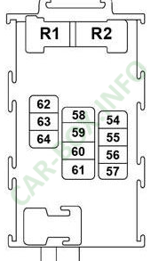
Present primarily on models equipped with an Idle Stop/Start system.
| Diagram | |
|---|---|
|
|
| No. | Circuit Protected / Description |
| 54 | 10A Steering angle sensor |
| 55 | 10A Diode |
| 56 | 10A Audio system, Around View Monitor (AVM), radar distance sensor, front camera |
| 57 | 10A Engine Control Module (ECM), Transmission Control Module (TCM), transmission range switch, engine compartment fuse box, neutral position switch, primary speed sensor, secondary speed sensor, vehicle speed sensor, reverse lamp switch |
| 58 | Not used |
| 59 | 10A Air conditioning system |
| 60 | 10A ABS control module, Vehicle Dynamic Control (VDC) |
| 61 | Not used |
| 62 | Not used |
| 63 | 20A Audio system, navigation control module, Around View Monitor (AVM) |
| 64 | Not used |
| R1 – Auxiliary relay | |
| R2 – Ignition relay | |
Engine Compartment Fuse Boxes
The engine compartment houses four power distribution units: two main fuse boxes located adjacent to the battery, a fuselink block mounted directly on the positive battery terminal, and an auxiliary fuse box located behind the front bumper under the headlight assembly.
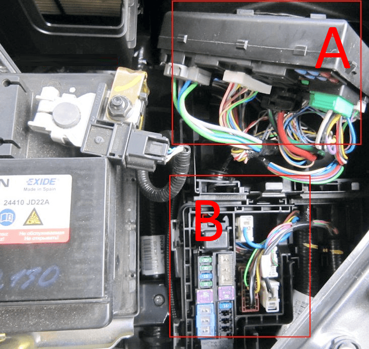
Under-hood distribution box locations (Nissan X-Trail T32).
Fuse Box A
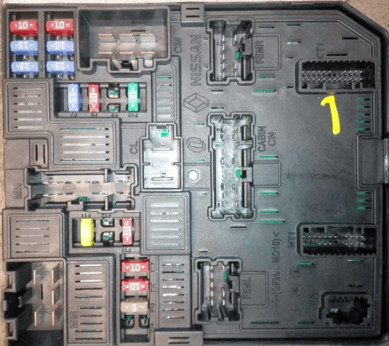
General layout.
| Diagram | |
|---|---|

|
|
| No. | Circuit Protected / Description |
| 81 | 10A Engine Control Module (ECM) |
| 82 | 15A Engine Control Module (ECM) |
| 83 | 15A Electronic throttle control actuator, ECM, EVAP canister purge valve, Mass Air Flow (MAF) sensor, ignition coils, main relay, intake/exhaust variable valve timing solenoids, high-pressure fuel pump, fuel injectors, engine compartment fuse box, air-fuel ratio sensor, fuel heater, water-in-fuel sensor, coolant bypass valve |
| 84 | 10A ECM, intake manifold runner control valve, variable valve timing (VVT) solenoids |
| 85 | 15A Air-fuel ratio (AFR) sensor, heated oxygen sensor (HO2S), turbocharger boost control solenoid, ECM, glow plug control module |
| 86 | 15A Fuel injectors, ignition coils, fuse box |
| 87 | 15A A/C compressor clutch relay |
| 88 | Not used |
| 89 | Not used |
| 90 | 30A Windshield wiper relay, windshield wiper motor |
| 91 | 20A Fuel pump relay |
| 92 | Not used |
| 93 | 10A Engine Control Module (ECM), Transmission Control Module (TCM), transmission range switch, engine compartment fuse box, neutral position switch, primary speed sensor, secondary speed sensor, tachometer speed sensor, park/neutral position switch |
| 94 | Not used |
| 95 | 5A Electric steering column lock module |
| 96 | 10A Restart relay (Idle Stop/Start system) |
| 97 | 10A Right front combination lamp, left front combination lamp, A/C compressor clutch, transmission range switch, engine compartment fuse box, neutral position switch, reverse lamp switch, park/neutral position switch |
Fuse Box B

Diagram.
| No. | Circuit Protected / Description |
| 41 | 15A Horn |
| 42 | 30A R9M engine: PTC heater relay 2 |
| 43 | 30A R9M engine: PTC heater relay 3 |
| 44 | 30A R9M engine: PTC heater relay 1 |
| 45 | 30A Electric parking brake |
| 46 | 30A Auxiliary connector |
| 47 | 15A Horn |
| 48 | 30A Electric parking brake |
| F | 50A Electronic Stability Program (ESP) |
| 50A R9M engine: Power windows, panoramic sunroof, power sunshade, power seats | |
| G | 30A ABS control module |
| H | 50A ESP control module |
| 30A R9M engine: Radiator cooling fan relay | |
| I | 30A Starter motor |
| 50A R9M engine: ESP control module | |
| J | 30A Power liftgate |
| 50A R9M engine: ESP control module | |
| K | 40A ABS control module |
| 30A R9M engine: Radiator cooling fan relay | |
| L | 30A Starter motor, fuse box (E14) |
| M | 50A Power windows, panoramic sunroof, power sunshade, power seats |
| 40A R9M engine: ABS control module |
Auxiliary Fuse Box (Behind Front Bumper)
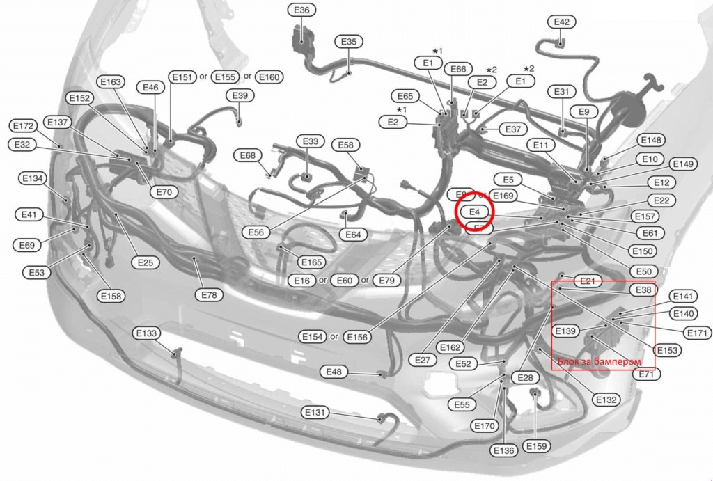
Location.

Photo example.

Diagram on the inside of the cover.
Battery Terminal Fuselink Block
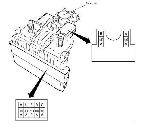
Mounted directly on the positive battery terminal.
This article is for reference only. Always verify fuse designations against the legend printed on the protective cover of your vehicle's fuse box.

doing a great job
Keep up the good works