Most of the electrical circuits in the Japanese crossover are protected by fuses. Headlights, fan motors, fuel pump and other powerful current consumers are connected via relays. Protective elements are installed in distribution boxes, which are located under the hood and in the passenger compartment.
In this article, we will take a detailed look at the fuse box diagrams for the Nissan X-Trail T31 2007, 2008, 2009, 2010, 2011, 2012, 2013, 2014, 2015 release.
In the engine compartment
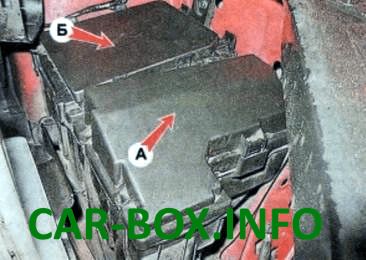
In the engine compartment, the protective elements are installed in the main A and additional B distribution boxes, which are located under the air intake.
Fuse box A
Type 1
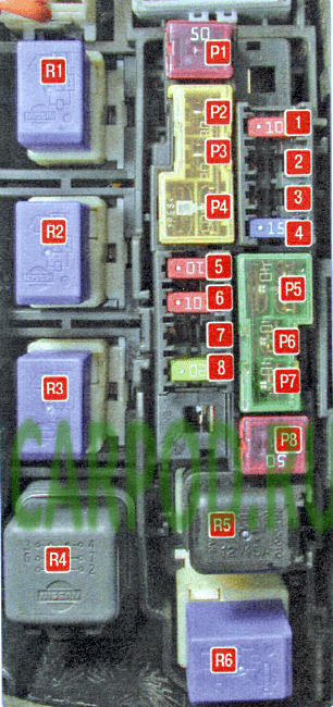
Diagram
| No. | Decoding | A |
| 1 | Variator ECU (CVT) | 10 |
| 2 | Heated rear seats | 20 |
| 3 | Additional heater (diesel engine) | 30 |
| 4 | Audio system | 15 |
| 5 | Sound signal generator | 10 |
| 6 | Daylight, horn | 10 |
| 7 | Turbocharger cooling electric pump (diesel engine) | 20 |
| 8 | Heated front seats | 20 |
| P1 | ABS system (ESP) | 50 |
| P2 | 30 | |
| P3 | Headlight washers | 30 |
| P4 | Electric power steering | 60 |
| P5 | Engine cooling fan | 40 |
| P6 | Ignition switch (lock) | 40 |
| P7 | Engine cooling fan | 40 |
| P8 | Power window control unit | 50 |
| Relay | ||
| R1 | Outdoor lighting relay | |
| R2 | headlight washer | |
| R3 | Cooling Fan Low Speed Relay | |
| R4 | brake light activation, additional heater (diesel engine) | |
| R5 | sound signal | |
| R6 | High Speed Relay for Engine Cooling Fan | |
Type 2
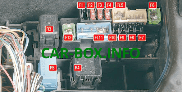
Diagram.
| № | Legend |
| F1 | 20A Air cooler turbine (turbodiesel) |
| F2 | 10A Transmission mode switch block (vehicles with four-wheel drive) |
| F3 | 10A Generator |
| F4 | 10A Sound signal |
| FL5 | 60 / 30A Electric power steering, headlight washer pump, ABS system |
| F6 | 40A ABS system, stability control system |
| F7 | 30A Electric cabin heater (for a car with a diesel engine) |
| F8 | 30A Electric cabin heater |
| F9 | 30A Electric cabin heater |
| F10 | Spare |
| FL11 | 50/30 / 40A Engine cooling fan, ignition |
| F12 | 40A Control unit for electrical interior equipment |
| R3 | Horn relay |
| R4 | Engine cooling fan relay |
| R5 | Headlight washer pump relay |
Fuse box B
Type 1
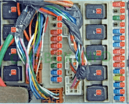
Diagram.
| No. | Description | A |
| 1 | Empty | - |
| 2 | - | |
| 3 | High beam (right) | 10 |
| 4 | High beam (left) | 10 |
| 5 | parking lights | 10 |
| 6 | Backlight | 10 |
| 7 | Empty | - |
| 8 | Windshield wiper | 20 |
| 9 | Low beam (right) | 10 |
| 10 | Low beam (left) | 10 |
| 11 | A / C compressor clutch | 10 |
| 12 | Empty | - |
| 13 | Spare | 30 |
| 14 | Empty | - |
| 15 | Heated side mirrors and tailgate glass | 15 |
| 16 | 15 | |
| 17 | Gasoline pump | 15 |
| 18 | Automatic transmission operating mode sensor, starter winding relay | 10 |
| 19 | ABS control unit / ABS system | 10 |
| 20 | Reversing lights | 10 |
| 21 | Engine ECU | 15 |
| 22 | Engine ECU, ignition coil control system | 15 |
| 23 | Diagnostic oxygen concentration sensor | 20 |
| 24 | Injector control system | 15 |
| 25 | Fog lights | 15 |
| Relay | ||
| R1 | Fog lights | |
| R2 | low beam | |
| R3 | Engine ECU relay | |
| R4 | heated side mirrors and tailgate glass | |
| R5 | starter | |
| R6 | cooling fan | |
| R7 | ||
| R8 | ||
| R9 | ignition | |
Type 2
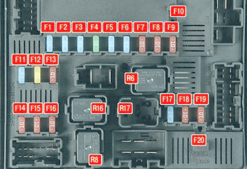
Diagram.
| № | Description |
| F1 | 15A Window heater |
| F2 | 15A Window heater |
| F3 | 15A Fog lights |
| F4 | 30A Windshield wiper |
| F5 | 15A Low beam lamp, right headlight |
| F6 | 15A Low beam lamp, left headlight |
| F7 | 10A High beam lamp, right headlight |
| F8 | 10A High beam lamp, left headlight |
| F9 | 10A Side light bulbs |
| F10 | Empty |
| F11 | 15A Transmission control |
| F12 | 20A Engine control unit |
| F13 | 10A A / C compressor |
| F14 | 10A Reversing lamps |
| F15 | 10A Gearbox |
| F16 | 10A Engine management system |
| F17 | 15A Fuel pump |
| F18 | 10A Power system (fuel injectors) |
| F19 | 10A Hydro electronic unit ABS |
| F20 | Empty |
| R6 | Ignition system relay |
| R8 | Tailgate glass heater relay |
| R16 | Engine cooling fan low speed relay I |
| R17 | Engine cooling fan II high speed relay |
Power fuse panel
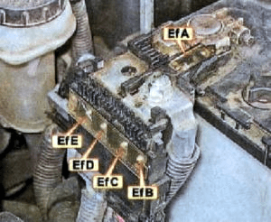
On the positive terminal of the storage battery there are fuses in the form of high-power fuses.
- EfA - 250 / 140A alternator, EBfB and EBfC fuse circuits
- EfB - 100A engine compartment fuse block
- EfC - 100A lighting, air conditioning
- EfD - 80 / 100A ignition relay, engine compartment fuse circuit
- EfE - 80 / 100A Engine Compartment Fuse Block
- EfN - 60A glow plug control unit
In the passenger compartment
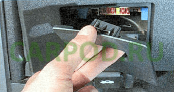
The fuse box is located under the cover in the opening of the lower trim of the instrument panel.
Type 1
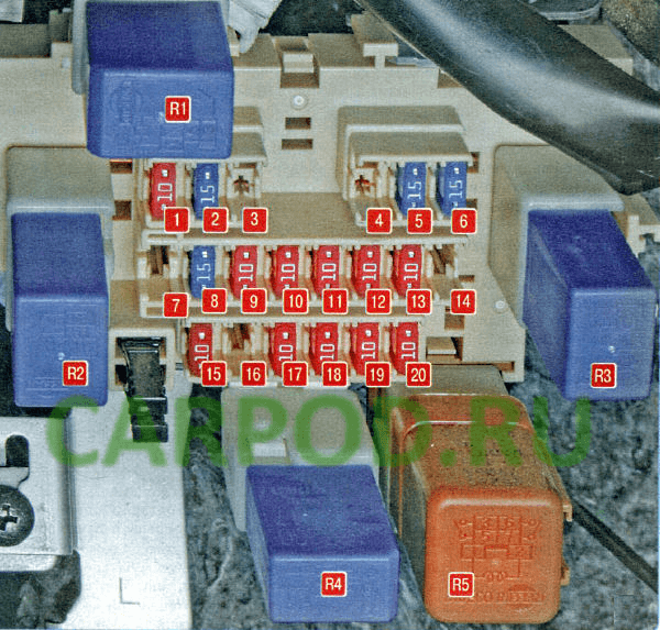
Diagram.
| No. | Description | A |
| 1 | Power mirrors, audio system | 10 |
| 2 | Power Outlets | 15 |
| 3 | cigarette lighter fuse Trail 31 | 10 |
| 4 | Empty | - |
| 5 | Air conditioner fan | 15 |
| 6 | 15 | |
| 7 | Keyless Access System | 10 |
| 8 | Upper auxiliary headlights | 15 |
| 9 | All-wheel drive control unit | 10 |
| 10 | Stop lights | 10 |
| 11 | Interior lighting | 10 |
| 12 | Instrument cluster | 10 |
| 13 | Electrical control unit | 10 |
| 14 | Audio system | 10 |
| 15 | Heated side mirrors | 10 |
| 16 | Audio system | 20 |
| 17 | Washer pump | 10 |
| 18 | Instrument cluster | 10 |
| 19 | Airbags | 10 |
| 20 | Diagnostic connector, engine ECU, headlight electro corrector | 10 |
| Relay | ||
| R1 | Relay for switching on upper auxiliary headlights | |
| R2 | Optional equipment | |
| R3 | Switching on the air conditioner fan | |
| R4 | Switching on the seat heating | |
| R5 | Switching on the upper auxiliary headlights | |
Type 2

Diagram.
| № | Description |
| F1 | 10A Audio system, electric drive of outside mirrors |
| F2 | 15A Front socket (cigarette lighter) |
| F3 | 15A Cigarette lighter |
| F4 | 10A Air conditioning, electric cabin heater |
| F5 | 15A Heater motor |
| F6 | 15A Heater motor |
| F7 | 10A Optional equipment |
| F8 | 15A CVT sensors (mechanical gearbox) |
| F9 | 15A Audio system |
| F10 | 10A Brake lights |
| F11 | Spare |
| F12 | 10A Control unit for electrical equipment of the passenger compartment |
| F13 | 10A Electrical equipment |
| F14 | 15A Rear socket (if installed) |
| F15 | 10A Heated mirrors |
| F16 | 10A Control unit for electrical equipment of the passenger compartment |
| F17 | 15A Electrical equipment |
| F18 | 20A Moto windshield wiper gear |
| F19 | 10A SRC airbags |
| F20 | 10A Heated seats |
| R1 | Relay additional equipment of salon |
| R2 | Heater fan relay |
