Nissan Note belongs to subcompact vans. The first generation is designated as E11 and was produced in 2005, 2006, 2007, 2008, 2009, 2010, 2011, 2012 and 2013. During this period, the car was restyled. The second generation E12 has been produced since 2012. We present for review information about the locations of all major electronic control units. We will pay special attention to fuses and relays for the Nissan Note e11, we will show photographs of the blocks and their diagrams with decoding.
The purpose of the elements of your blocks and their meaning may differ from the one presented. Check the description with yours on the back of the protective cover.
In the passenger compartment
General arrangement
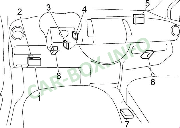
Location of control units.
|
|
| № | Description |
| 1 | Fuse box |
| 2 | Door Lock Relay (with Intelligent Car Access System) |
| 3 | Theft Deterrent System Antenna Amplifier (NATS) |
| 4 | Intelligent car access control unit |
| 5 | Body Electronics Module (BCM) |
| 6 | Transmission control unit |
| 7 | Airbag unit |
| 8 | ESP control unit |
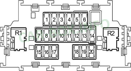
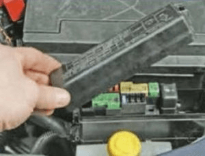
Fuse box
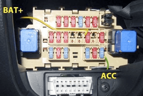
Located in the instrument panel, on the left behind the protective cover.
| Diagram | |
|---|---|
|
|
| № | Legend |
| F1 | 10A Airbags SRC system |
| F2 | 10A Bodywork, Ignition Relay, Fuel Pump Relay, Body Electronics Module (BCM) |
| F3 | 10A warning indicators, warning buzzer, charging system |
| F4 | 15A Windshield and tailgate washer pump |
| F5 | 15A Heated exterior mirrors |
| F6 | 10A Anti-theft system (NATS), Audio system |
| F7 | 10A Body electronics module (BCM) |
| F8 | 10A Central locking, remote control unit |
| F9 | 10A Brake lights, ABS, ESP, warning indicators |
| F10 | Reserve |
| F11 | Reserve |
| F12 | 10A Interior lighting, remote control unit, lighting, luggage compartment lighting, rain sensor |
| F13 | Reserve |
| F14 | 10A Instrument panel illumination, diagnostic connector (OBD II), intelligent car access system, direction indicators |
| F15 | 15A Electric fan heater |
| F16 | 10A Climatic unit |
| F17 | 15A Electric fan heater |
| F18 | 15A Rear socket |
| F19 | 10A Heated seats |
| F20 | 15A Front outlet, cigarette lighter fuse |
| Relay | |
| R11 | Heater fan relay |
| R12 | Interior auxiliary equipment relay |
For the front cigarette lighter, there is a 15A fuse number 20.
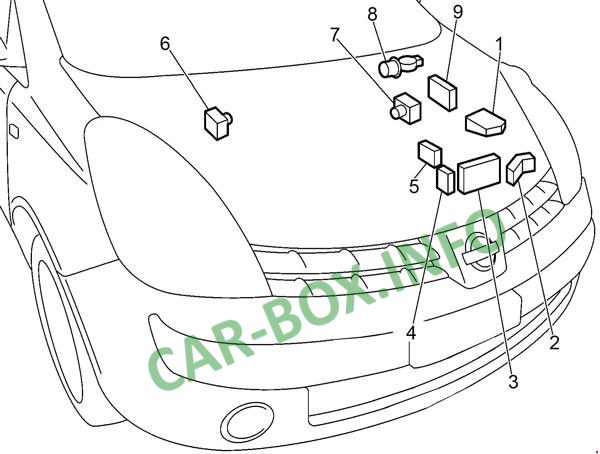
In the engine compartment
General arrangement
Location of electronic components.
|
|
| № | Legend |
| 1 | Fuse distribution box (IPDM E / R) |
| 2 | Relay box (PTC) |
| 3 | Additional fuse box |
| 4 | K9K : Additional power fuse box |
| 5 | Power fuse box |
| 6 | LHD: ABS control unit |
| 7 | RHD: ABS control unit |
| 8 | Wiper motor |
| 9 | Engine control unit (ECM) |
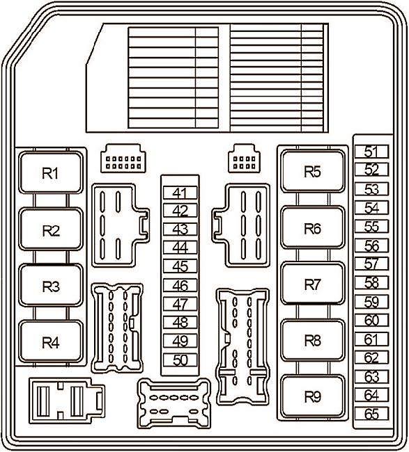
Fuse box #1
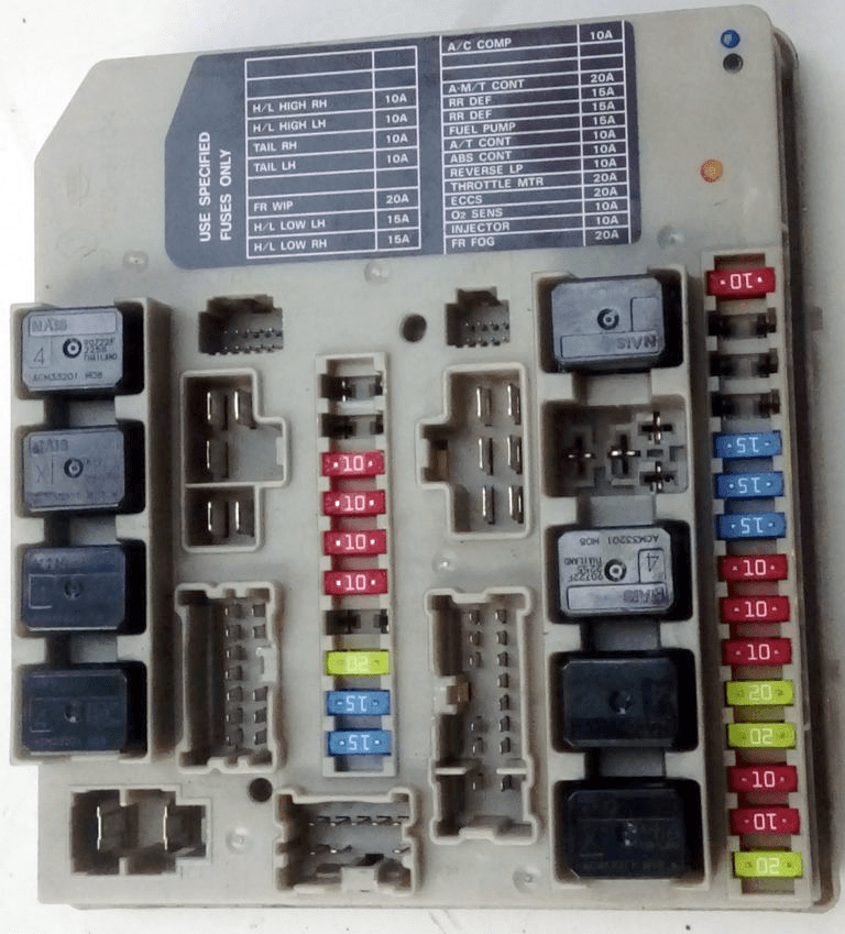
Fuse distribution box №1 - photo.
| Diagram | |
|---|---|
|
|
| № | Description |
| 41 | - |
| 42 | - |
| 43 | 10A High beam right, daytime running lights, automatic lighting system |
| 44 | 10A High beam left, daytime running lights, automatic lighting system |
| 45 | 10A Side light on the right side, automatic lighting system, backlight |
| 46 | 10A Side light on the left side, automatic lighting system, lights, headlights |
| 47 | - |
| 48 | 20A Windshield wiper and washer |
| 49 | 15A Low beam left, daytime running lights, automatic lighting system |
| 50 | 15A Low beam right, daytime running lights, automatic lighting system |
| 51 | 10A A / C compressor clutch |
| 52 | - |
| 53 | - |
| 54 | 20A Automatic transmission control unit |
| 55 | 15A Heated rear window, fuse No. 5 (heated mirrors) |
| 56 | 15A Heated rear window, fuse No. 5 (heated mirrors) |
| 57 | 15A Fuel pump relay |
| 58 | 10A Speed sensor (automatic transmission), oil temperature sensor (automatic transmission), automatic transmission control unit, turbine rotation sensor |
| 59 | 10A ABS, ESP |
| 60 | 10A Automatic transmission selector, starting system, reversing lamps, automatic transmission indicators, rear wiper and washer |
| 61 | 20A Throttle valve relay |
| 62 | 20A Engine control unit, MAF sensor, crankshaft position sensor, camshaft position sensor, canister purge valve, ignition system, intake valve, anti-theft system, injectors, fuel drive, turbine valve |
| 63 | 10A Fuel injection system, front heated oxygen sensor, rear heated oxygen sensor |
| 64 | 10A Fuel injection system |
| 65 | 20A Front fog light |
| Relay | |
| R1 | 1) Heated rear window, 2) Dipped beam |
| R2 | 1) Engine control unit (ECM), 2) Side light |
| R3 | 1) Low beam, 2) High beam left |
| R4 | 1) Front fog light, 2) High beam right |
| R5 | 1) Starter, 2) A / C compressor clutch |
| R6 | Front fog light |
| R7 | 1) Cooling fan (high speed), 2) Windshield wiper |
| R8 | 1) Cooling fan (low speed), 2) Cooling fan (high speed) |
| R9 | 1) Ignition, 2) Cooling fan (low speed) |
Fuse box #2
| Diagram | |
|---|---|

|
|
| № | Description |
| 31 | - |
| 32 | - |
| 33 | - |
| 34 | 15A Audio system |
| 35 | 10A Sound signal |
| 36 | 10A charging system |
| 37 | 10A Daytime running lights |
| 38 | - |
| F | 40A ABS, ESP |
| G | 40A Cooling fan relay (high speed), cooling fan relay (low speed) |
| H | 40A Ignition lock |
| I | 40A Auxiliary heater (PTC) |
| J | 40A Power windows, body electronics module (BCM) |
| K | 30A ABS, ESP |
| L | 30A Headlight cleaners |
| M | 60A Power steering |
| R1 | Daytime Running Lights |
| R2 | Sound signal |
Power fuse panels
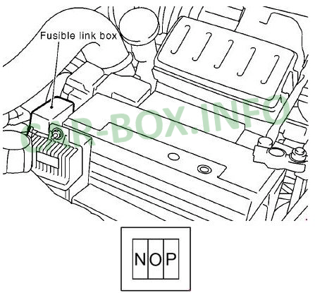
- N 80A - Auxiliary heater (PTC)
- O 60A - Glow plugs
- P 80A - Auxiliary heater (PTC)
Located on the positive battery circuit.
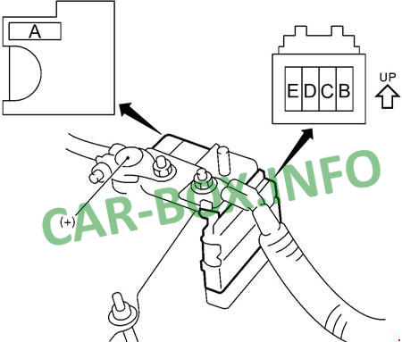
- А - 80/140 / 250А - Charging system, starting system, fuses;
- B - 80 / 100A - Fuses;
- C - 80A - Fuses;
- D - 60A - Ignition relay, fuses, fuel pump relay;
- E - 80A - Auxiliary relay, fuses, heater relay.

Why is there no Nissan Safari vvt 4800 2022 - 2005 and I have to say the truth is the best site for specifications and standards and to know what we need during the holidays %,100
Thank you