
The Nissan Primera was manufactured across three generations in sedan, station wagon, and hatchback body styles. The first generation (P10) was produced from 1990 to 1995; the second generation (P11) from 1996 to 2000; and the third generation (P12) from 2001 to 2007.

Below is detailed technical information regarding the fuse and relay boxes for the third-generation Nissan Primera (chassis code P12; MS platform), including location photos, terminal diagrams, and circuit assignments. Specific locations for the cigarette lighter fuses are also highlighted.
Passenger Compartment
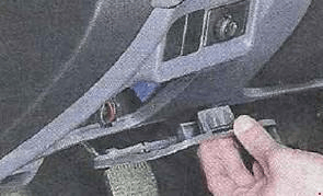
The fuse box is located inside the dashboard behind an access cover. A circuit designation diagram detailing element assignments is printed on the reverse side of the cover.
| Diagram | |
|---|---|
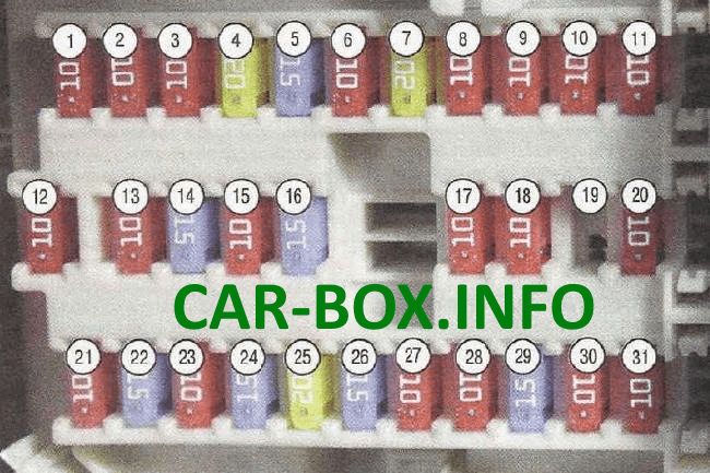
|
|
| No. / Rating | Circuit / Component Description |
| 1 - 10A | Audio System |
| 2 - 10A | Cruise Control |
| 3 - 10A | Trunk Latch Actuator |
| 4 - 20A | Trunk Power Outlet |
| 5 - 15A | Stop Lamps (Brake Lights) |
| 6 - 10A | Front Fog Lamps |
| 7 - 20A | Heated Rear Window (Tailgate Glass) |
| 8 - 10A | Heated Front Seats |
| 9 - 10A | Cruise Control Module |
| 10 - 10A | Electronic Control Units (ECU) Power Supply |
| 11 - 10A | Automatic Transmission Control Module (TCM) |
| 12 - 10A | Electronic Components Power Supply |
| 13 - 10A | Interior / Dome Lighting |
| 14 - 15A | HVAC Blower Motor |
| 15 - 10A | Air Conditioning System (A/C) |
| 16 - 15A | HVAC Blower Motor |
| 17 - 10A | Engine Control Module (ECM) |
| 18 - 10A | Supplemental Restraint System (SRS / Airbags) |
| 19 | Spare |
| 20 - 10A | Engine Control Module (ECM) |
| 21 - 10A | Starter Solenoid Relay |
| 22 - 15A | Cigarette Lighter |
| 23 - 10A | Power Exterior Mirrors |
| 24 - 15A | Center Console Power Outlet |
| 25 - 20A | Windshield Wipers |
| 26 - 15A | Windshield and Rear Window Washers |
| 27 - 10A | Vehicle Sensors |
| 28 - 10A | Rear Window Wiper Motor |
| 29 - 15A | Fuel Pump |
| 30 - 10A | Instrument Cluster |
| 31 - 10A | Anti-lock Braking System (ABS) |
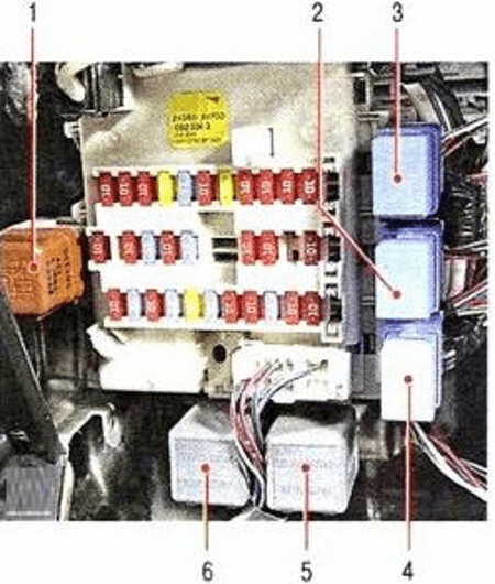
Relays located on the front of the fuse box panel:
- Rear window defogger relay
- Throttle actuator motor relay
- Front fog lamp relay
- Power window relay
- Turn signal / Flasher relay
- Turn signal / Flasher relay
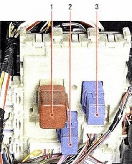
Relays located on the reverse side of the fuse box panel:
- Ignition relay
- Accessory (ACC) relay
- HVAC blower motor relay
Engine Compartment
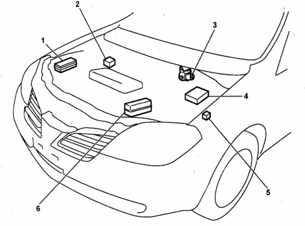
Location overview.
Fuse Box
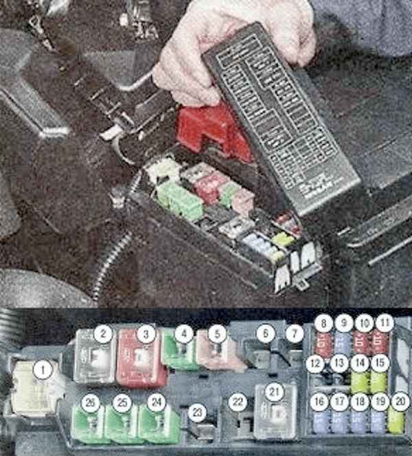
Fuse box diagram.
| No. / Rating | Circuit / Component Description |
| 1 - 120A | Main Fuse 1 |
| 2 - 80A | Ignition-Switched Power Supply |
| 3 - 50A | ABS Hydraulic Pump Motor |
| 4 - 40A | Ignition Switch |
| 5 - 30A | ABS Solenoid Valves |
| 6 | Spare |
| 7 | Spare |
| 8 - 10A | Parking / Clearance Lamps |
| 9 - 15A | Audio System |
| 10 - 10A | Engine Control Module (ECM) |
| 11 - 15A | Horn |
| 12 | Spare |
| 13 | Spare |
| 14 - 15A | Low Beam Headlamp (Left) |
| 15 - 15A | Low Beam Headlamp (Right) |
| 16 - 15A | Electronic Throttle Control Motor |
| 17 - 15A | High Beam Headlamp (Left) |
| 18 - 15A | High Beam Headlamp (Right) |
| 19 - 15A | Front Fog Lamps |
| 20 - 20A | Ignition Coils |
| 21 - 80A | Main Fuse 2 |
| 22 | Spare |
| 23 - 30A | Headlamp Washers |
| 24 - 40A | Radiator Cooling Fan Motor 2 |
| 25 - 40A | Radiator Cooling Fan Motor 1 |
| 26 - 40A | Power Windows |
Relay Box
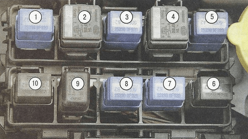
Relay box diagram.
| No. | Relay Function |
| 1 | Front fog lamp relay |
| 2 | Radiator cooling fan relay |
| 3 | Accessory (ACC) relay |
| 4 | Radiator cooling fan relay |
| 5 | A/C compressor magnetic clutch relay |
| 6 | Radiator cooling fan relay |
| 7 | Park/Neutral Position (PNP) relay (Automatic Transmission / CVT) |
| 8 | Daytime Running Lights (DRL) / Low beam relay |
| 9 | Horn relay |
| 10 | Radiator cooling fan relay |
