The Vectra C made its official debut at the Geneva Motor Show in 2002. The model is built on the GM Epsilon platform. It was initially available as a four-door sedan and a five-door hatchback known as the GTS. A five-door station wagon was added in October 2003. In this article, we will take a detailed look at the fuse box diagrams for the Opel / Vauxhall Vectra C (third generation) 2002, 2003, 2004, 2005, 2006, 2007, 2008, 2009, 2010 years of manufacture.
Here you will find the locations and photos of distribution boxes. The fuses responsible for the “Cigarette lighter” and “Fuel Pump” are highlighted in bold.
In the engine compartment
There are two distribution boxes here that are responsible for protecting the electrical circuits.
The main unit
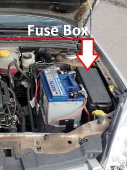
It is located near the battery and is covered with a plastic cover.
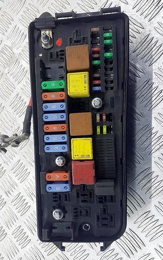
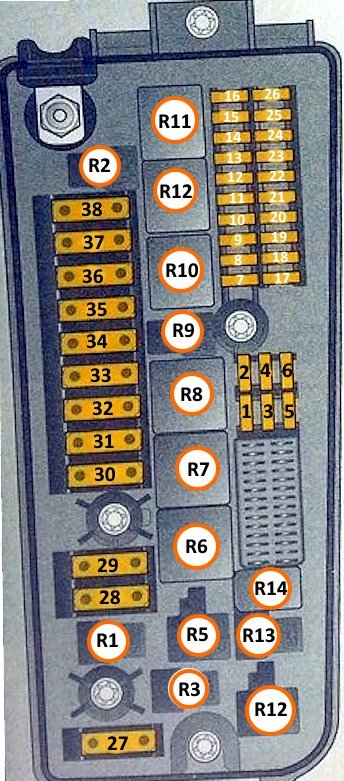
General view.
| Diagram | ||
|---|---|---|
|
||
| No. | Description of fuses/relays | Amps |
| 1 | Engine ECU | 20 |
| 2 | Starter | 25 |
| 3 | Horn | 20 |
| 4 | Air conditioning - climate control | 10 |
| 5 | Windshield cleaner/washer | 15 |
| 6 | Spare | - |
| 7 | ESP (stable stability control) | 15 |
| 8 | Headlights, windscreen washer nozzle heaters | 10 |
| 9 | Power steering | 7.5 |
| 10 | Headlights corrector | 10 |
| 11 | Windshield cleaner | 30 |
| 12 | 30 | |
| 13 | ESP (stable stability control) | 7.5 |
| 14 | Engine control | 10 |
| 15 | Engine ECU | 10 |
| 16 | Brake system (ABS) | 7.5 |
| 17 | Spare | - |
| 18 | - | |
| 19 | Headlight Corrector Control Unit, Headlight Corrector, Xenon Headlights | 5 / 10 15 |
| 20 | Headlights corrector | 5 |
| 21 | Spare | - |
| 22 | - | |
| 23 | Additional heater | 20 |
| 24 | Battery voltage | 30 |
| 25 | 30 | |
| 26 | Spare | - |
| 27 | - | |
| 28 | Boot lid (tailgate) opening/closing actuator control unit | 60 |
| 29 | Brake system (ABS) | 40 |
| 30 | Boot lid (tailgate) opening/closing actuator control unit | 60 |
| 31 | Interior fuse/relay box | 60 |
| 32 | Brake system (ABS) | 40 |
| 33 | Main Ignition Relay, Fuse/Relay Box, Instrument Panel | 60 |
| 34 | Boot lid (tailgate) opening/closing actuator control unit | 60 |
| 35 | Cooling fan motor | 30 / 40 |
| 36 | 20 / 30 | |
| 37 | Adaptive headlight system - AFL | |
| 38 | Spare | - |
| R1 | Empty | |
| R2 | Empty | |
| R3 | Empty | |
| R4 | Empty | |
| R5 | Engine control relay | |
| R6 | Starter relay | |
| R7 | Windshield Wiper Motor Relay (ON/OFF) | |
| R8 | Empty | |
| R9 | Main ignition circuit relay | |
| R10 | Windscreen wiper motor relay (low/high wiper speed) | |
| R11 | Headlight washer relay | |
| R12 | Empty | |
| R13 | Empty | |
| R14 | Air conditioner compressor clutch relay | |
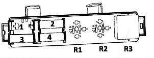
Auxiliary unit
Located near the main fuse box.
| Diagram | |
|---|---|
|
|
| Type 1 | |
| No. | Purpose |
| R2/R3 | Fuel heater relay |
| 1 | Empty |
| 2 | Starter 30A |
| 3 | Empty |
| 4 | Horn 20A |
| Type 2 | |
| No. | Purpose |
| 1 | Empty |
| 2 | Glow plug control unit 60A |
| 3 | Fuel filter heater relay 30A |
| 4 | Glow plug control unit 60A |
| R3 | Fuel filter heater relay |
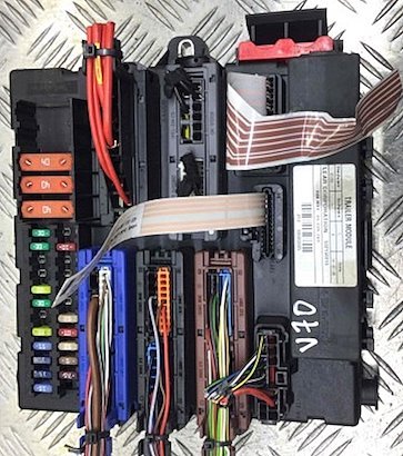
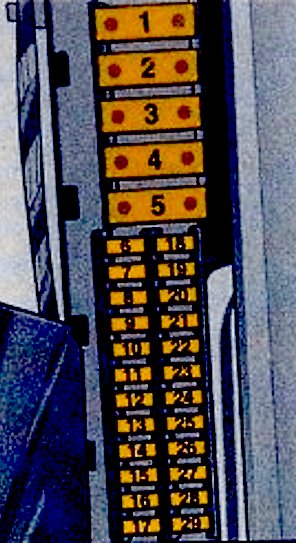
In the passenger compartment
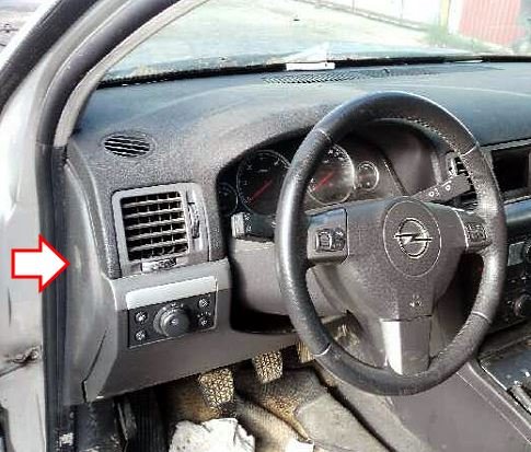
The distribution box is located in the left end on the driver's side of the dashboard, and is covered with a plastic cover.
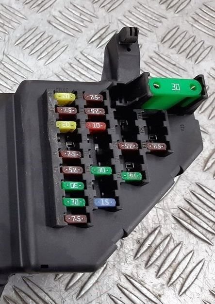
General view of the Opel / Vauxhall Vectra C interior fuse box.
| Diagram | ||
|---|---|---|

|
||
| No. | Description | Amps |
| 1 | Audio system, auxiliary heater, DVD player | 20 |
| 2 | Air Conditioning - Temperature Control, A/C/Heater Fan Motor | 7.5 |
| 3 | Sunroof | 20 |
| 4 | Spare | - |
| 5 | Door electrical control unit | 7.5 |
| 6 | Brake lights | 7.5 |
| 7 | Multifunction control unit 1 | 30 |
| 8 | Door electrical control unit | 30 |
| 9 | Multifunction control unit 1 | 7.5 |
| 10 | Steering column electrical control unit | 7.5 |
| 11 | Diagnostic connector (DLC) | 7.5 |
| 12 | Protection against overloading the battery | 15 |
| 13 | Spare | - |
| 14 | - | |
| 15 | Driver's door electrical control unit | 30 |
| 16 | Spare | - |
| 17 | Instrument cluster, multifunction display | 15 |
| 18 | Ignition switch, air conditioning | 7.5 |
| 19 | Spare | - |
| 20 | Lateral movement sensor | 7.5 |
| 21 | Telematics | 7.5 |
| 22 | Vectra C cigarette lighter fuse | 30 |
| 23 | Air conditioner - temperature control, air conditioner/heater fan motor | 30 |
| 24 | Reserve | - |
| 25 | Air Conditioning - Temperature Control, A/C/Heater Fan Motor | 7.5 |
| 26 | Multifunction display, instrument cluster | 7.5 |
| Relay on the back of the block | ||
|
||
| 1 | Ignition circuit (Terminal 15a) | |
| 2 | Terminal 15 | |
| 3 | interior ventilation | |
| 4 | heater fan | |
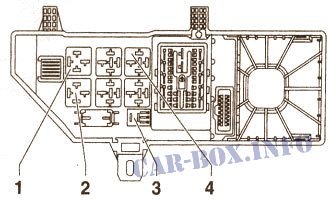
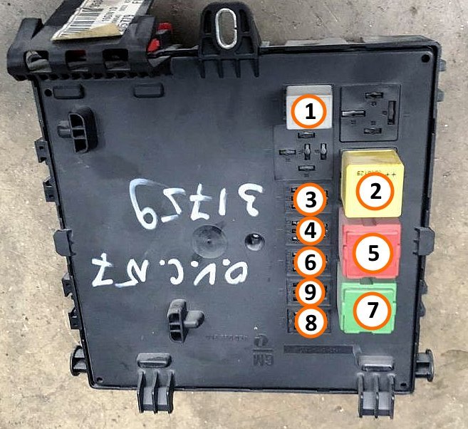
In the luggage compartment
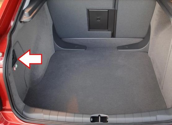
The distribution box is located in the luggage compartment on the left side, behind the duffle box.
General view.
| Diagram | ||
|---|---|---|
|
||
| No. | Decoding | Amps |
| 1 | Reserve | - |
| 2 | - | |
| 3 | Power seat drive | 40 |
| 4 | Rear window heater | 40 |
| 5 | Power seat drive | 40 |
| 6 | Power window lifter - right rear window | 30 |
| 7 | Power window lifter - left rear window | 30 |
| 8 | Seat heater, rear right | 15 |
| 9 | Anti-theft system, buzzer | 15 |
| 10 | Opel / Vauxhall Vectra C fuel pump fuse | 20 |
| 11 | Battery voltage | 25 |
| 12 | Heated seat - rear left | 12 |
| 13 | Trailer electrical connector | 20 |
| 14 | Rear window wiper | 15 |
| 15 | Heated seats, seat ventilation system, front left seat | 10 |
| 16 | Heated seat, rear right | 15 |
| 17 | Optional equipment connection socket | 15 |
| 18 | Boot lid / tailgate lock | 30 |
| 19 | Battery voltage | 10 |
| 20 | central locking | 7.5 |
| 21 | Volume change sensor (anti-theft system) | 5 |
| 22 | Remote control of the boot lock | 30 |
| 23 | Anti-theft glass system wire (anti-theft glass break sensor) | 7.5 |
| 24 | Battery voltage | 25 |
| 25 | Suspension control system | 10 |
| 26 | Ignition lock | 25 |
| 27 | Seat occupant sensor, tyre pressure monitoring system, rain sensor, air conditioning system | 5 |
| 28 | Parking sensors | 7.5 |
| 29 | Reserve | - |
| Relay at the back of the unit | ||
|
||
| No. | Purpose | |
| 1 | Rear window wiper | |
| 2 | Terminal 15 | |
| 3 | Rear left seat heater | |
| 4 | Rear right seat heater | |
| 5 | Rear window heating | |
| 6 | Horn/anti-theft alarm | |
| 7 | Fuel module (fuel pump relay) | |
| 8 | Central locking / fuel filler flap cover | |
| 9 | Not used | |

1.9tdi won't start