
The Skoda Fabia is a subcompact (B-segment) car produced by Czech manufacturer Škoda Auto since 1999. This guide details the fuse box and relay panel diagrams for the second-generation Škoda Fabia (PQ24 platform: 5J2 hatchback and 5J5 Combi estate) for model years 2007 through 2010, as well as facelifted models from 2011 to 2015.
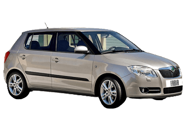
Below you will find the locations and photographs of the electrical distribution panels. Fuses for the “Cigarette Lighter” and “Fuel Pump” are highlighted in bold.
Engine Compartment
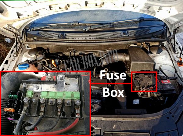
Fuse box located on top of the battery.
Type 1
Fuse panel layout.

|
||
| No. | Description | A |
| 1 | Alternator | 175 |
| 2 | Spare | |
| 3 | Interior power supply (Terminal 30) | 80 |
| 4 | Auxiliary electrical heater | 60 |
| 5 | Interior power supply (Terminal 30) | 40 |
| 6 | Radiator cooling fan, glow plugs | 50 |
| 7 | Electro-hydraulic power steering system | 50 |
| 8 | ABS, ESP, ASR systems | 25 |
| 9 | Radiator cooling fan | 30 |
| 10 | 5 | |
| 11 | ABS, ESP, ASR control unit | 40 |
| 12 | Central control unit (BCM) | 5 |
| 13 | Automatic transmission control module | 5 |
| Auxiliary heater | 40 | |
Type 2
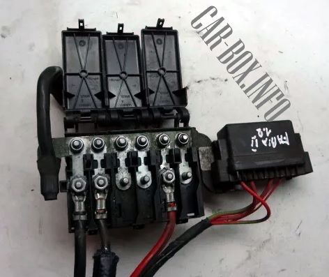
Example shown above.
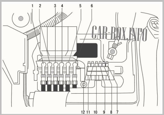
| Diagram | ||
|---|---|---|
|
||
| No. | Description | A |
| 1 | Alternator | 175 |
| 2 | On-board power supply control unit (BCM) | 80 |
| 3 | Auxiliary heater | 60 |
| 4 | ABS electro-hydraulic unit | 40 |
| 5 | Power steering control unit | 50 |
| 6 | Glow plug control unit | 50 |
| 7 | Automatic transmission control unit | 5 |
| 8 | On-board power supply control unit (BCM) | 40 |
| 9 | Radiator cooling fan | 30 |
| 10 | Air conditioning system | 5 |
| 11 | Radiator cooling fan | 30 |
| 12 | ABS electro-hydraulic unit | 25 |
Passenger Compartment
The passenger compartment houses two distribution boxes that protect the vehicle’s electrical circuits.
Fuse Box

Located on the driver’s side under the dashboard behind a protective plastic cover.
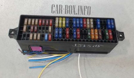
Overview of the Škoda Fabia passenger compartment fuse box.
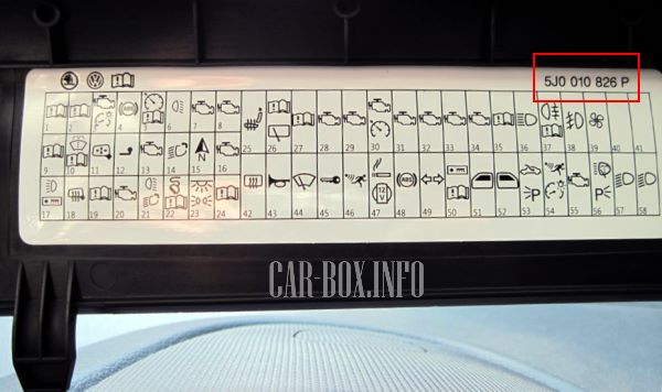
The inside of the protective cover features a fuse assignment diagram with corresponding part numbers:
- 5J0 010 623 A / 5J0 010 675: Models from 2007 to 2010,
- 5J0 010 743: Models from 2010 to 2012,
- 5J0 010 826 P: Models from 2012 to 2015,
| Diagram | ||
|---|---|---|
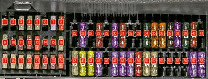
|
||
| No. | Description | A |
| 1 | Spare | - |
| 2 | Spare | - |
| 3 | Headlight range control adjuster | 5 |
| 4 | ABS electro-hydraulic unit | 5 |
| 5 | Cruise control system | 5 |
| 6 | Spare | - |
| 7 | Engine Control Unit (ECU) – BBM, BZG engines | 15 |
| 8 | Fuel injectors – BXW, BTS engines | 10 |
| 9 | Park assist control unit, climate control module | 5 |
| 10 | Spare | - |
| 11 | Power mirror control module, power window control module | 7.5 |
| 12 | Reversing lamps | 7.5 |
| 13 | Automatic transmission control module (TCM) | 15 |
| 14 | Dynamic cornering light actuator | 10 |
| 15 | Navigation system | 5 |
| 16 | Electro-hydraulic power steering control unit | 5 |
| 17 | License plate lights, left parking light | 5 |
| 18 | Right parking light | 5 |
| 19 | Audio system head unit | 5 |
| 20 | Engine Control Unit (ECU) – BXW, BTS engines | 5 |
| 21 | Brake lights (stop lights) | 10 |
| 22 | Climate control module, park assist, telephone interface, steering angle sensor, central electrical control unit | 7.5 |
| 23 | Interior lighting | 7.5 |
| 24 | Tailgate lock release | 10 |
| 25 | Heated seats | 20 |
| 26 | Windscreen washer system | 15 |
| 27 | Spare | - |
| 28 | EVAP canister purge valve (AKF) | 10 |
| 29 | Fuel injectors – BBM, BZG engines | 10 |
| 30 | Fuel pump | 15 |
| 31 | Oxygen (Lambda) sensors | 10 |
| 32 | Spare | - |
| 33 | - | |
| 34 | Engine Control Unit (ECU) – BXW, BTS engines | 30 |
| 35 | Instrument cluster and switch illumination | 5 |
| 36 | Main beam (high beam) headlights | 15/5 |
| 37 | Rear fog lamp | 7.5 |
| 38 | Front fog lights | 10 |
| 39 | Heater / climate control blower motor | 30 |
| 40 | Rear window wiper motor | 30 |
| 41 | Spare | - |
| 42 | Heated rear window | 25 |
| 43 | Horn | 20 |
| 44 | Windscreen wipers | 20 |
| 45 | On-board power supply control unit (BCM) | 15 |
| 46 | Spare | - |
| 47 | Cigarette lighter (Škoda Fabia Mk2) | 15 |
| 48 | ABS electro-hydraulic unit | 15 |
| 49 | Turn signals / hazard warning lights | 15 |
| 50 | Radio / Navigation system head unit | 10 |
| 51 | Left door power window control module | 25 |
| 52 | Right door power window control module | 25 |
| 53 | Electric sunroof | 25 |
| 54 | Interior monitoring / Ultrasonic alarm sensor (if equipped) | 15 |
| 55 | Spare | - |
| 56 | Headlight washer system | 25 |
| 57 | Left dipped (low) beam headlight | 15 |
| 58 | Right dipped (low) beam headlight | 15 |
Relay Panel
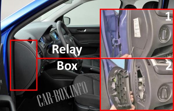
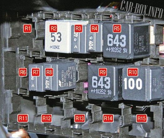
The relay panel is located at the left end of the dashboard. Remove the plastic side trim cover to gain access.
| Diagram | |
|---|---|
|
|
| No. | Function |
| R1 R6 R11 -R15 |
Spare |
| R2 | Heated windscreen (if equipped) |
| R3 | Starter interlock |
| R4 | Fuel line pressurization supply |
| R5 | Main power supply (Terminal 30) |
| R7 | Front position lights |
| R8 | Fuel pump relay |
| R9 | Air conditioning compressor clutch |
| R10 | “X” contact load reduction relay |

Thank you soo much this is very helpfull
Finding a Type 2 replacement is almost impossible