
In 1999, as part of the Volkswagen Group, Škoda launched a new model line called the Fabia as the successor to the Felicia. Built on the VW Polo platform, the Fabia was produced in several body styles. In this article, we provide detailed fuse box diagrams and terminal layouts for the Škoda Fabia (PQ24 platform; 6Y2 hatchback, 6Y5 Combi station wagon, and 6Y3 sedan) covering model years 1999, 2000, 2001, 2002, 2003, and 2004, as well as the facelifted models from 2005, 2006, 2007, and 2008.
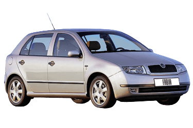
Below you will find the locations and photos of the power distribution boxes. Fuses controlling the “Cigarette lighter” and “Fuel pump” circuits are highlighted in bold.
In the engine compartment
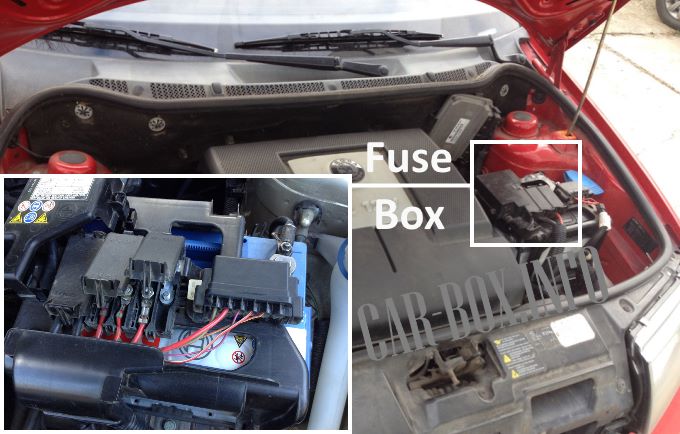
The main engine compartment fuse box is mounted directly on top of the battery unit. It consists primarily of high-current fusible links.
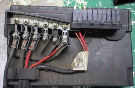
General view.
Type 1
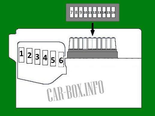
Diagram.
| No. | Description | A |
| 1 | Alternator | 110 150 170 |
| 2 | Auxiliary heater relays 1 and 2, light switch, instrument panel fuse/relay box 1 (F1–5 and F39–45), auxiliary ignition relays, ignition switch | 110 |
| 3 | Power steering control module | 50 |
| 4 | Glow plugs, secondary air injection pump motor | 40 |
| 5 | Radiator fan motor | 40 |
| 6 | Anti-lock braking system (ABS) | 40 |
| 7 | 25 | |
| 8 | Radiator fan motor | 30 |
| 9 | Empty | |
| 10 | Multifunction control unit 1 | 5 |
| 11 | Air conditioning system | 5 |
| 12 | Empty | |
| 13 | Automatic transmission control unit | 5 |
| 14 | Empty | |
| 15 | Empty | |
| 16 | Empty |
Type 2
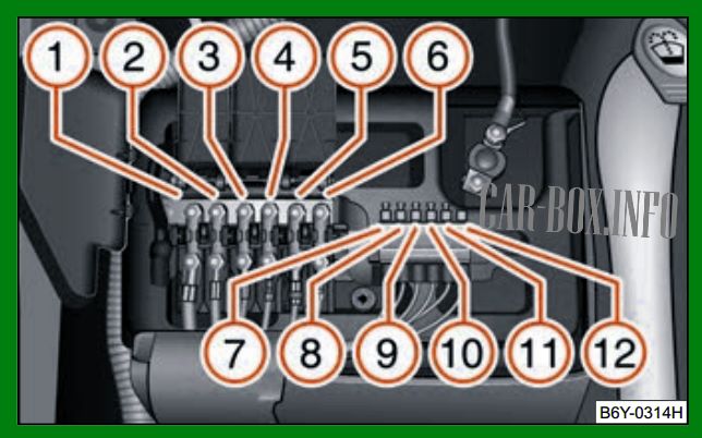
Diagram.
| No. | A | Description |
| 1 | 175 | Alternator |
| 2 | 110 | Passenger compartment fuse box |
| 3 | 40 | Radiator fan |
| 4 | 40 | ABS / TCS / ESP systems |
| 5 | 50 | Power steering pump |
| 6 | 50 | Glow plugs (1.9L / 96 kW diesel engine only) |
| 7 | 25 | ABS / TCS / ESP systems |
| 8 | 30 | Radiator fan |
| 9 | 5 | Air conditioning system |
| 10 | 15 | Engine control unit (ECU) |
| 11 | 5 | Central control unit |
| 12 | 5 | Automatic transmission control unit |
In the passenger compartment
The passenger compartment contains two power distribution centers protecting the vehicle’s electrical circuits.
Fuse box
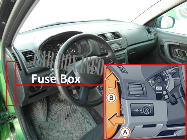
Located on the driver's side end of the dashboard. Access it by unclipping the dashboard side access panel.
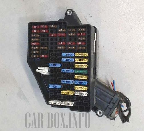
General view of the Škoda Fabia passenger compartment fuse box.
| Diagram | ||
|---|---|---|
|
||
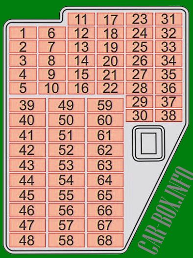
| No. | Description | A |
| 1 | Anti-lock braking system (ABS/ESP), instrument cluster | 5 |
| 2 | Brake lights | 10 |
| 3 | Air conditioning, Data Link Connector (DLC / Diagnostic port) | 5 |
| 4 | Interior lighting | 10 |
| 5 | Door open warning contact switch | 5 |
| 6 | Headlight range control unit | 5 |
| 7 | Engine management unit, power steering module | 5 |
| 8 | Power steering system | 10 |
| 9 | Heated oxygen sensor (Lambda sensor) | 10 |
| 10 | Terminal S (ignition switch logic signal), audio system, instrument cluster | 5 |
| 11 | Power mirrors, heated door mirrors | 5 |
| 12 | Air conditioning system, recirculated air flap actuator, navigation system, telephone unit | 5 |
| 13 | Reversing lights | 10 |
| 14 | Engine management system – Diesel | 10 |
| 15 | Windscreen wiper / washer system | 10 |
| 16 | Instrument cluster | 5 |
| 17 | Engine management system – Petrol | 5 |
| 18 | Telephone / hands-free interface | 5 |
| 19 | Automatic transmission control unit | 10 |
| 20 | Bulb monitoring control unit | 5 |
| 21 | Automatic transmission selector control, heated windscreen washer nozzles, sunroof | 5 |
| 22 | Empty | - |
| 23 | Right headlight (high beam) | 10 |
| 24 | Engine management system | 10 |
| 25 | Anti-lock braking system (ABS) | 5/10 |
| 26 | Empty | - |
| 27 | Empty | - |
| 28 | Brake light switch (brake pedal position sensor), clutch pedal position sensor, cruise control system (CCS) | 5 |
| 29 | Empty | - |
| 30 | High beam indicator light, left headlight (high beam) | 10 |
| 31 | Tailgate / luggage compartment lock actuator | 10 |
| 32 | Rear window wiper / washer system | 10 |
| 33 | Right parking lights (front and rear) | 5 |
| 34 | Left parking lights (front and rear) | 5 |
| 35 | Fuel injectors – Petrol | 10 |
| 36 | Number plate lights | 5 |
| 37 | Rear fog light | 5 |
| 38 | Power mirror adjustment / mirror heating | 5 |
| 39 | Heated rear window | 20 |
| 40 | Horn | 20 |
| 41 | Windscreen wiper / washer system | 20 |
| 42 | Škoda Fabia cigarette lighter fuse | 15 |
| 43 | Multifunction control unit 1, automatic transmission selector lever switch | 20 |
| 44 | Turn signals / hazard warning lights | 15 |
| 45 | Audio system, navigation unit | 20 |
| 46 | Front right power window | 25 |
| 47 | Empty | - |
| 48 | Engine management system – Diesel | 30 |
| 49 | Central locking system | 15 |
| 50 | Headlight range control, right headlight (low beam) | 15 |
| 51 | Power socket for optional accessories | 15 |
| 52 | Engine management system – Petrol | 15 |
| 53 | Rear right power window | 25 |
| 54 | Headlight range control, left headlight (low beam) | 15 |
| 55 | Empty | - |
| 56 | Engine management system – Petrol | 20 |
| 57 | Trailer electrical towing socket | 25 |
| 58 | Front left power window | 25 |
| 59 | CD changer, audio system | 20 |
| 60 | Anti-theft alarm system | 15 |
| 61 | Škoda Fabia fuel pump fuse | 15 |
| 62 | Sunroof | 25 |
| 63 | Heated front seats | 15 |
| 64 | Headlight washer system | 20 |
| 65 | Front fog lights | 15 |
| 66 | Rear left power window | 25 |
| 67 | Empty | |
| 68 | Fresh air blower fan (heating and air conditioning) | 25 |
Relay box

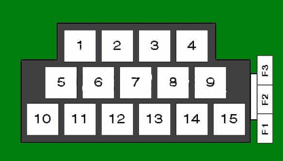
The main relay carrier is located under the dashboard on the driver's side.
| Diagram | |
|---|---|
|
|
| F1 | (40 A) Auxiliary heater fuses |
| F2 | |
| F3 | |
| 1 | Fuel pump relay (diesel, ATD engine up to 07/00) |
| 2 | Empty |
| 3 | Glow plug relay |
| 4 | Empty |
| 5 | Door open warning relay |
| 6 | Headlight washer pump relay |
| 7 | Starter interlock relay |
| 8 | Auxiliary heater relay 1, low heating output (diesel) |
| 9 | Auxiliary heater relay 2, high heating output (diesel) |
| 10 | Empty |
| 11 | Terminal 15 auxiliary circuit / ignition relief relay |
| 12 | Engine management control unit relay (diesel, ASY / ATD engines up to 07/00) |
| 13 | Bulb monitoring control unit |
| 14 | |
| 15 | Škoda Fabia fuel pump relay (petrol, ARV / AME / AUA / AUB / AQV / ATZ / AQW engines up to 01/00) |
All electrical equipment
General component layout of the electrical system throughout the vehicle.

1. Air conditioning control module – integrated into heater control panel;
2. Anti-theft alarm control module – integrated into multifunction control unit 2;
3. Anti-theft alarm horn / siren (up to 07/00);
4. Anti-theft alarm horn / siren (from 08/00 onwards);
5. Battery;
6. Central locking control module – integrated into multifunction control unit 2;
7. Diagnostic link connector (DLC / OBD port) – behind glove compartment;
8. Front left door control module (central locking / power mirror / power window);
9. Front right door control module (central locking / power mirror / power window);
10. Rear left door control module (central locking / power mirror / power window);
11. Rear right door control module (central locking / power window);
12. Radiator fan control module – models equipped with air conditioning;
13. Passenger compartment fuse box (Box No. 1);
14. Passenger compartment relay carrier (Box No. 2);
15. Engine compartment fuse box – mounted above battery;
16. Auxiliary fuse (10 A) – rear of navigation control module;
17. Fresh air blower control unit / blower series resistor – blower unit, left side;
18. Heater control module – in heater control panel (models without air conditioning);
19. Horn;
20. Immobilizer reader coil – adjacent to ignition lock switch;
21. Hazard / turn signal relay – integrated into multifunction control unit 1;
22. Instrument cluster control module – behind dashboard panel (functions: immobilizer, warning lights, indicators);
23. Lights-on warning buzzer – integrated into instrument cluster;
24. Multifunction control unit 1 – located beneath relay carrier 2 under dashboard (functions: tailgate release actuator, cruise control system, heated rear window, horn, turn indicators / hazard lights, interior lighting, rear wiper, reversing lights (manual transmission), windscreen washer, windscreen wipers);
25. Multifunction control unit 2 – (functions: anti-theft alarm system, central locking, power / heated door mirrors, power windows);
26. Navigation control module – integrated into navigation/radio unit panel;
27. Parking distance control (PDC) module;
28. Parking distance control (PDC) buzzer – adjacent to interior dome light;
29. Power steering control module;
30. Heated seat control module – under driver's seat;
31. Heated seat control module – under passenger seat;
32. Left side impact airbag sensor – under front seat;
33. Right side impact airbag sensor – under front seat;
34. Airbag control module (SRS) – behind center console;
35. Sunroof control module – behind interior dome light;
36. Telephone interface module;
37. Transmission control unit (TCU);
38. Vehicle speed sensor (VSS) – transmission mounted.
