Skoda Rapid premiered in the fall of 2012 at the Paris Motor Show. In the model range of the Czech manufacturer, the novelty was placed between Fabia and Octavia. A year later, a hatchback version was presented. In this article, we will take a detailed look at the fuse box diagrams for the Skoda Rapid (body index NH1/NH3) 2012, 2013, 2014, 2015 years of manufacture.

Here you will find the locations and photos of distribution boxes. The fuses responsible for the “Cigarette lighter” and “Fuel Pump” are highlighted in bold.
In the passenger compartment
There are two distribution boxes here that are responsible for protecting the electrical circuits.
Fuse box
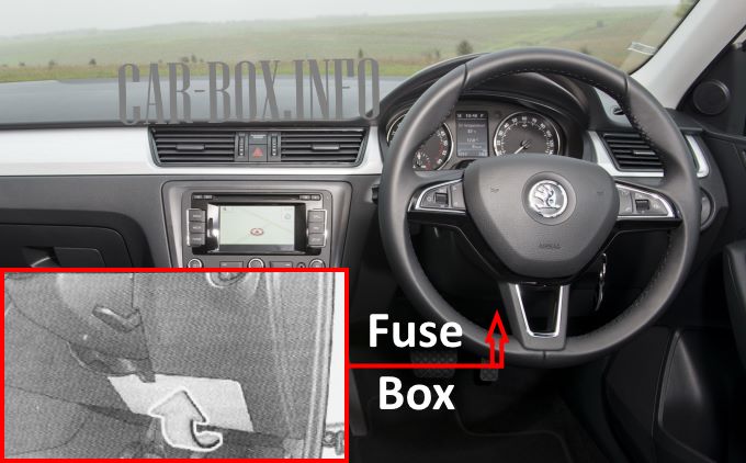
Located on the driver's side under the dashboard, behind the protective cover.
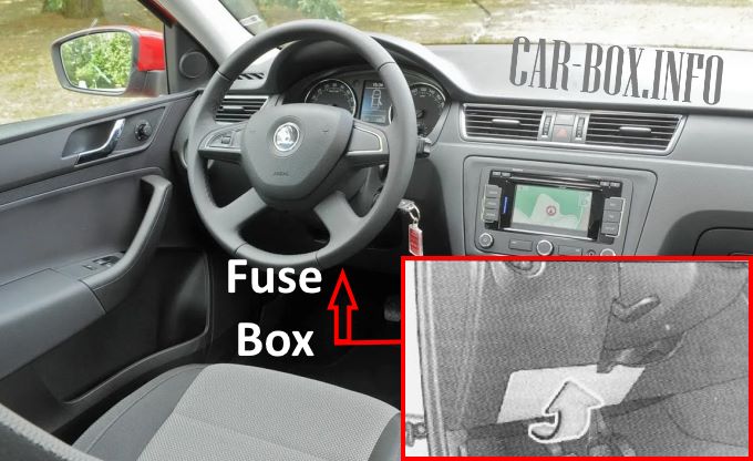
Location of the unit in left-hand drive vehicles.
Example of access.
| Diagrams | ||
|---|---|---|
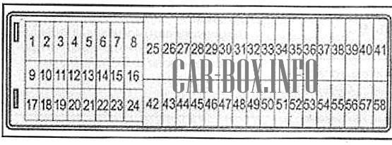
Left hand drive. |
||

Right hand drive. |
||
| No. | Description | A |
| 1 | Contact S | 5 |
| 2 | Start/Stop system | 5 |
| 3 | Instrument cluster, headlight corrector, telephone, oil level gauge | 7.5 |
| 4 | ABS / ESC control unit | 5 |
| 5 | Gasoline engine: cruise control | 5 |
| 6 | Reversing light (MCP) | 10 |
| 7 | Ignition, engine control unit, automatic transmission | 10 |
| 8 | Brake pedal limit switch, clutch pedal switch, radiator fan | 5 |
| 9 | Heater control, climate control control unit, parktronic, power windows, radiator fan, windshield washer nozzles | 5 |
| 10 | DC / DC converter | |
| 11 | Rear view mirror adjustment | 5 |
| 12 | Trailer detection control unit | |
| 13 | Automatic transmission selector, automatic transmission control unit | 10 |
| 14 | Headlights corrector | 10 |
| 15 | Spare | 5 |
| 16 | Power steering, speed sensor, engine-ECU | 10 |
| 17 | Head unit (start-stop), daylight mode | 5 |
| 18 | Heated mirrors | 7.5 |
| 19 | Ignition lock | 15 |
| 20 | Engine control unit, fuel pump control unit, fuel pump | 15 |
| 21 | Reverse lamp (automatic transmission), fog lamps with CORNER function | 10 |
| 22 | Climate control unit, heater control, instrument cluster, telephone, steering angle sensor, multifunction steering wheel, ignition key removal interlock | 7.5 |
| 23 | Interior, load box and trunk lighting, parking lights | 15 |
| 24 | Central control unit | 5 |
| 25 | Spare | |
| 26 | Rear wipers | 15 |
| 27 | Spare | |
| 28 | Gasoline engine adsorber solenoid valve, PTC auxiliary electric heater | 10 |
| 29 | Injection, coolant pump | 10 |
| 30 | Fuel pump fuse, cruise control, ignition | 20 |
| 31 | Lambda probe | 10 |
| 32 | Pressure valve, high-pressure fuel pump | 20 |
| 33 | Engine control unit | 20 |
| 34 | Vacuum pump, engine control unit | |
| 35 | Switch illumination, parking lights, license plate illumination, headlight cleaning system | 5 |
| 36 | High beam | 15 |
| 37 | Rear fog light, DC-DC converter | 5 |
| 38 | Fog lights | 10 |
| 39 | Heater fan | 30 |
| 40 | Spare | |
| 41 | Heated front seats | 20 |
| 42 | Rear window heating | 30 |
| 43 | Horn | 15 |
| 44 | Windshield wiper | 30 |
| 45 | Trunk lock, central locking | 20 |
| 46 | Alarm signal | 7.5 |
| 47 | Rapid cigarette lighter fuse, power outlet in the luggage compartment | 15 |
| 48 | ABS | 15 |
| 49 | Direction indicators, brake lights | 15 |
| 50 | DC-DC converter, head unit | 10 |
| 51 | Power windows (driver's door and rear left door) | 30 |
| 52 | Power windows (passenger door and right rear door) | 30 |
| 53 | Washer | 15 |
| 54 | Start/Stop system instrument cluster, paddle shifter unit, multifunction steering wheel | 5 |
| 55 | automatic transmission control unit | 30 |
| 56 | headlight washer | 25 |
| 57 | Left headlight dipped beam | 15 |
| 58 | Right headlight dipped beam | 15 |
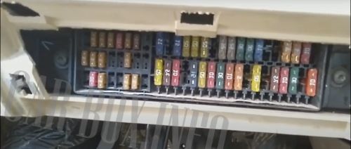
Additional relay block
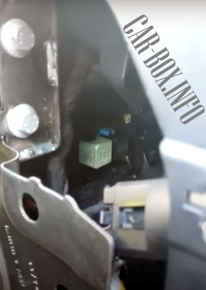
Relay modules are located behind the main fuse block on a special block. For easier access to it, you can remove a part of the trim from the end.
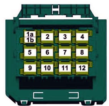
List of items in this unit: 1A - Fuel (Gasoline) pump relay 1B - Local relay 5 - High voltage heating element relay (PTC) 6/645 - Headlight washer
In the engine compartment
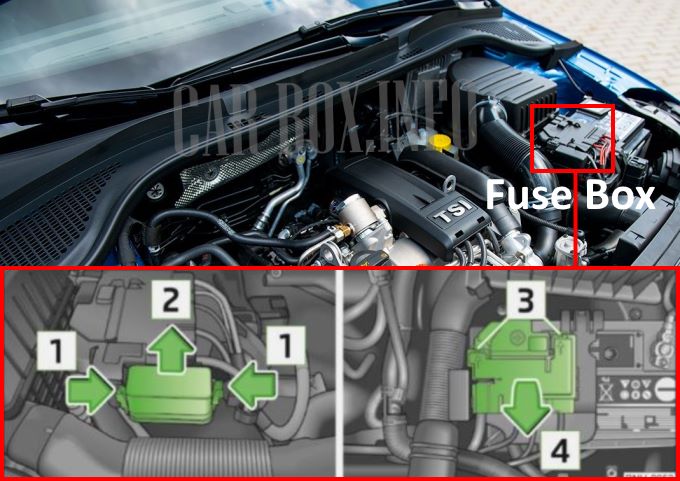
Type 1: near the battery, consists of fusible links and an additional unit placed next to it.
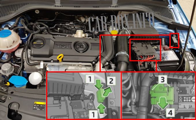
Type 2: busible links on the battery, additional board on the side.
| Engine compartment fuse diagram | ||
|---|---|---|

|
||
| No. | Description | A |
| 1 | Alternator | 175 |
| 2 | Reserve | 80 |
| 3 | Interior (type 1), fuse box power supply (type 2) | 60 |
| 4 | Electric auxiliary heater (type 1), interior (type 2) | 40 |
| 5 | Cabin | - |
| 6 | Radiator fan, glow plug control unit | - |
| 7 | Electro-hydraulic power steering | - |
| 8 | ABS | 30 |
| 9 | Radiator fan | - |
| 10 | automatic transmission | - |
| 11 | ABS | 5 |
| 12 | Central control unit | 40 |
| 13 | Additional electric heater | - |
