The second generation Octavia was introduced in March 2004. The model was based on the Volkswagen Group A5 (PQ35) platform. In this article, we will take a detailed look at the fuse box diagrams for the Skoda Octavia (codename A5) 2004, 2005, 2006, 2007, 2008, 2009, 2010, 2011, 2012, 2013 years of manufacture.
Here you will find the locations and photos of distribution boxes. The fuses responsible for the “Cigarette lighter” and “Fuel Pump” are highlighted in bold.
In the engine compartment
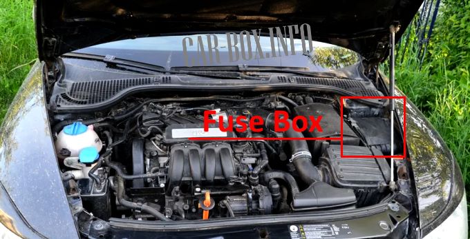
To gain access to the distribution box located in the engine compartment, slide the catches to unlock the cover and lift up to remove it.
| Diagram | ||
|---|---|---|
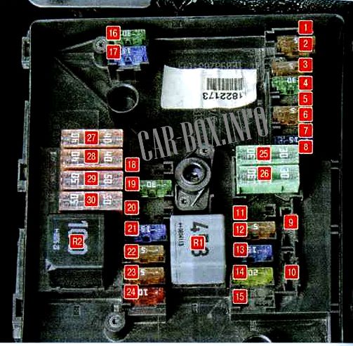
|
||
| No. | A | Decoding |
| 1 | - | Reserve |
| 2 | 5 | Handlebar switches |
| 3 | 5 | Diagnostic connector |
| 4 | 30 | Hydroelectronic module ABS |
| 5 | 15 | Automatic transmission control unit |
| 6 | 5 | Instrument cluster |
| 7 | - | Reserve |
| 8 | 15 | Audio system |
| 9 | 5 | Telephone |
| 10 | 5 | Engine control unit relay supply |
| 11 | 20 | Auxiliary heater and ventilation control unit |
| 12 | 5 | Data bus control unit |
| 13 | 15 | engine control unit |
| 14 | 20 | Ignition |
| 15 | 5, 15 | Oxygen concentration sensor, fuel pump relay, glow plug relay |
| 16 | 30 | ABS control unit |
| 17 | 15 | Horn (beep) |
| 18 | 30 | Sound amplifier |
| 19 | 30 | Windshield wipers |
| 20 | - | Reserve |
| 21 | 15 | Oxygen concentration sensor |
| 22 | 5 | Clutch / Brake Pedal Switch |
| 23 | 5, 10, 15 |
|
| 24 | 10 | EGR valve |
| 25 | 30 | Right headlight |
| 26 | 30 | Left headlight |
| 27 | 40 | Additional air pump, preheating |
| 28 | 40 | Starter |
| 29 | 50 | Terminal supply 30 |
| 30 | 50 | Clamp X * |
| R1 | - | Radiator fan motor relay |
| R2 | - | Automatic transmission control relay |
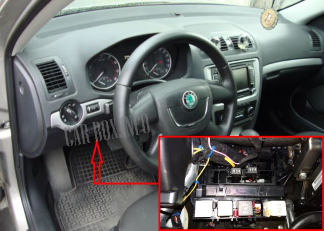
In the passenger compartment
There are two distribution boxes here that are responsible for protecting the electrical circuits.
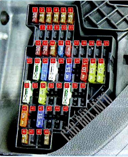
Main fuse block
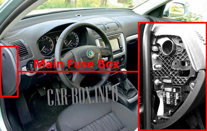
To gain access to the main cabin unit, carefully pry up the cover with a screwdriver and remove it.
| Diagram | ||
|---|---|---|
|
||
| No. | A | Description |
| 1 | 10 | Diagnostic connector, engine control unit, fuel pump |
| 2 | 5 | ABS, ESP control unit |
| 3 | 5 | Safety Airbags |
| 4 | 5 | Heater, air conditioner, reversing light lamp |
| 5 | 5 | Electric headlight corrector |
| 6 | 5 | Instrument cluster, automatic transmission control unit, electric power steering control unit, parking assist system |
| 7 | - | Empty |
| 8 | - | Empty |
| 9 | - | Empty |
| 10 | - | Empty |
| 11 | - | Empty |
| 12 | 10 | Central locking control unit |
| 13 | 10 | Outdoor lighting control unit, brake lights |
| 14 | 5 | Automatic transmission control unit, gear selector lock |
| 15 | 7.5 | Interior lighting control unit |
| 16 | 10 | Climate control system |
| 17 | - | Optional equipment |
| 18 | 5 | Parking assist sensors |
| 19 | 5 | Traction control unit |
| 20 | 5 | Hill start assist system |
| 21 | - | Empty |
| 22 | 40 | Climate control fan |
| 23 | 30 | Front power windows |
| 24 | 25 | Cigarette lighter fuse Skoda Octavia A5 |
| 25 | 25, 30 |
Rear window heater. Additional heater |
| 26 | 20 | Plug socket in the luggage compartment |
| 27 | 15 |
|
| 28 | - | Additional equipment |
| 29 | 10 | engine control unit |
| 30 | 20 | Automatic transmission control unit |
| 31 | 20 | Brake system vacuum pump |
| 32 | 30 | Rear power windows |
| 33 | 25 | Electric sunroof |
| 34 | 20 | Comfort function control unit |
| 35 | 5 | Anti-theft system |
| 36 | 20 | Headlight washers |
| 37 | 20 | Front seat heating |
| 38 | 30 | Rear seat heating |
| 39 | - | Empty |
| 40 | 40 | Heating fan |
| 41 | 15 | Tailgate window wiper |
| 42 | 15 | Windshield washer |
| 43 | 15 | Traction hitch |
| 44 | 20 | Traction hitch |
| 45 | 15 | Traction hitch |
| 46 | 5 | Heated windshield washer nozzles |
| 47 | 5 | Additional heater relay |
| 48 | - | Empty |
| 49 | 5 | Center light switch |
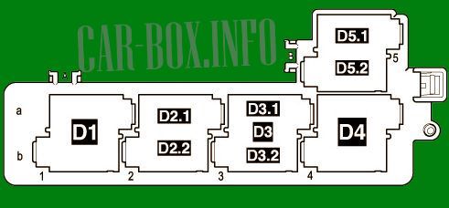
Auxilary relay block
An add-on board with relay modules is located under the steering wheel.
| Relay diagrams (Type 1) | |
|---|---|
| Top board | |
|
|
| No. | Description |
| D1 | Independent heater relay (on models with independent auxiliary heater) or Relay for low heat output (for models with auxiliary resistance heater (RTS)) |
| D2.1 | Horn |
| D2.2 | Fuel (Gasoline) pump relay (for BUD, CGGA, BSE, BSF, CMXA, CHGA engines) / Additional fuel pump relay -J832- (for CLCA, CLCB, CFHF, CFHC, CEGA engines) |
| D3 | Relay for high heat output (on models with optional resistance heater (RTS)) |
| D3.1 | Fresh air blower (for models with independent auxiliary heater) |
| D3.2 | Additional heater fuel pump relay -J749- (on models with independent additional heater) |
| D4 | Starter |
| D5.1 | Wiper relay |
| D5.2 | relay for the heating element (for motor letter designation CAYC) |
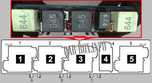
| Bottom board | |
|
|
| No. | Description |
| 1 | supply voltage relay (15) |
| 2 | rear window heater relay |
| 3 | supply voltage relay (50) starter relay 1 |
| 4 |
|
| 5 | switching relay for contact X |
| Relay diagram (Type 2) | |
|---|---|
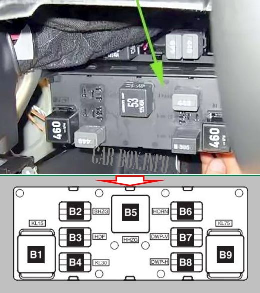
|
|
| B4 | supply voltage (30) |
| B5 | rear window heating |
| B6 | horn |
| B7 | window washer pump 1 |
| B8 | window washer pump 2 |
| B9 | switching relay for X contact |
