The Yeti compact SUV debuted at the Geneva Motor Show in 2009 as the first car of this class in Skoda's lineup. The pluses include a spacious interior and ease of getting in and out of both the first and second rows of seats. In this article, we will take a detailed look at the fuse box diagrams for the Skoda Yeti (1st generation; codename 5L) 2009, 2010, 2011, 2012, 2013, 2014, 2015, 2016, 2017, 2018 years of manufacture.

Here you will find the locations and photos of distribution boxes. The fuses responsible for the “Cigarette lighter” and “Fuel Pump” are highlighted in bold.
In the engine compartment
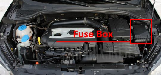
Located near the battery, behind the protective cover.
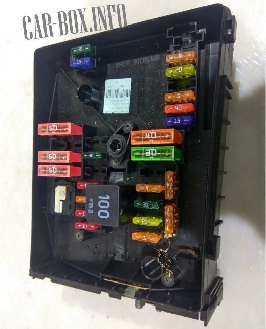
General view.
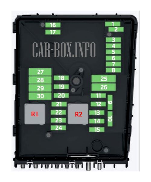
| Diagram | ||
|---|---|---|
|
||
| No. | Description | A |
| 1 | Empty | |
| 2 | DSG gearbox | 30 |
| 3 | Multifunctional control unit, | 5 |
| 4 | ABS / ESP system | 20 |
| 5 | DSG gearbox | 15 |
| 6 | Instrument panel, wiper switch handle and turn signal lever | 5 |
| 7 | Main ignition circuits | 40 |
| 8 | Radio | 15 |
| 9 | Telephone | 5 |
| 10 |
|
5 10 |
| 11 | Additional heater | 20 / 30 |
| 12 | Diagnostic unit | 5 |
| 13 | Engine management | 15 / 30 |
| 14 | Engine management, Ignition | 20 |
| 15 | Lambda probe, yeti fuel pump fuse or glow plug relay | 5 / 10 |
| 16 | Central on-board electrical control unit, right main headlamp, right rear grouped light unit | 30 |
| 17 | Horn (beep) | 15 |
| 18 | Digital processor amplifier for sound processing | 30 |
| 19 | Windshield wiper | 30 |
| 20 | Fuel pressure regulating valve | 15 / 10 / 20 |
| 21 | Lambda probe | 20 / 15 / 10 |
| 22 | Switch for clutch pedal, switch for brake control pedal | 5 |
| 23 | Coolant pump solenoid valve for boost pressure limitation, high-pressure fuel pump cooler switch valve | 15 / 10 / 5 |
| 24 | Activated carbon filter, exhaust gas recirculation valve | 10 |
| 25 | ABS / ESP system | 40 |
| 26 | Multifunctional control unit | 30 |
| 27 | Glow plugs, preheating | 50 |
| 28 | Heated windshield | 5 |
| 29 | Interior power supply | 50 |
| 30 | X contact | 50 |
| R1 | - | |
| R2 | Engine control relay | - |
In the passenger compartment
There are two distribution boxes here that are responsible for protecting the electrical circuits.
Fuse box
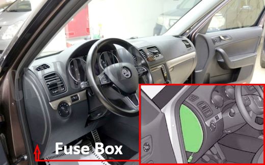
It is located at the end of the dashboard on the driver's side. It can be accessed by removing a part of the trim.
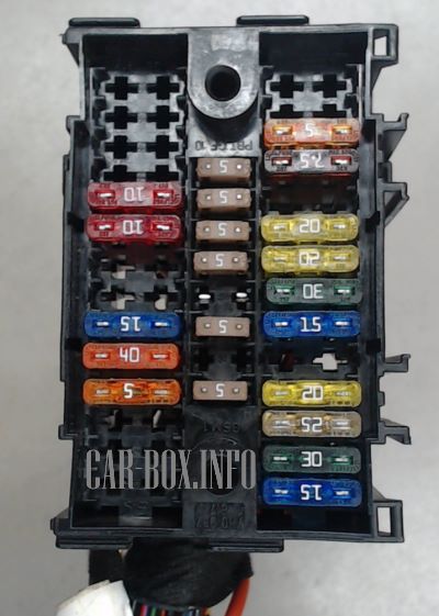
General view of the Skoda Yeti interior fuse box.
| Diagram | ||
|---|---|---|
|
||
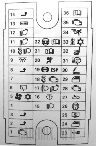
| No. | Decoding of fuses | A |
| 1 |
|
10 |
| 2 | Trailer control unit | 20 |
| 3 | 15 | |
| 4 | Instrument panel, wiper switch handle, turn signal switch lever | 5 |
| 5 | Heater fan, cooling fan, air conditioner, Сlimatronic | 40 |
| 6 | Rear window wiper | 15 |
| 7 | Telephone | 5 |
| 8 | Trailer control unit | 15 |
| 9 | Multifunctional control unit | 10 |
| 10 | Rain sensor, light switch, center plug for connection of a diagnostic test bench | 10 |
| 11 | Left headlight | 10 |
| 12 | Right headlight | 10 |
| 13 | Audio / navigation system | 15 |
| 14 | Towing and coupling device | 5 |
| 15 | Light switch | 5 |
| 16 | Windshield washer nozzle heaters | 5 |
| 17 | Headlights corrector | 5 |
| 18 | Center plug for connection of diagnostic test bench, engine control unit, brake sensor | 10 |
| 19 | ABS control unit, ESP, tire pressure monitoring switch, parking aid equipment control unit, Offroad mode switch, start and stop button | 5 |
| 20 | SRS system, Airbag system switch and control unit | 5 |
| 21 | WIV, reversing light, mirror darkening, pressure sensor, telephone preparation, air flow meter | 5 |
| 22 | Instrument panel, electromechanical power steering control unit, Haldex | 5 |
| 23 | Centrally controlled locking system and trunk lid | 15 |
| 24 | Rear window elevator | 30 |
| 25 | Rear window heating, independent auxiliary heater and ventilation | 25/30 |
| 26 | Power connector for optional equipment (trunk) | 20 |
| 27 | Electrically operated sliding and tilting sunroof in the vehicle roof, electrically operated sunshade | 30 |
| 28 | Fuel pump relay, gasoline pump control unit, valve injectors | 15 |
| 29 | Front window lifter | 30 |
| 30 | Skoda Yeti cigarette lighter fuse, front and rear | 20 |
| 31 | Headlight washer / washer system | 20 |
| 32 | Seat heater | 20 |
| 33 | Heater, Сlimatic, Сlimatronic | 7.5 |
| 34 | Anti-theft system | 5 |
| 35 | Transmission control | 10 |
| 36 | Audio system | 5 |
Relay box

An additional panel with relay modules is located near the main unit. In order to access it, a part of the front trim must be removed.

|
|
| 1 | Main ignition circuits |
| 2 | Rear window heating |
| 3 | Empty |
| 4 | Fuel pump relay |
| 5 | Ignition auxiliary circuits |
| F1 | Power seats - 30A |

great job