
Table of Contents
The Jimny is a compact body-on-frame SUV manufactured by the Japanese automaker Suzuki since 1970. In this article, we will provide a detailed breakdown of the fuse box diagrams for the fourth-generation Suzuki Jimny (chassis codes JB64/JB74) for the 2018, 2019, 2020, 2021, 2022, 2023, 2024, 2025, and 2026 model years.

Here you will find the locations and photos of the fuse and relay boxes. We will specifically highlight the fuses responsible for the 12 V power outlet (cigarette lighter) and the fuel pump.
Passenger Compartment
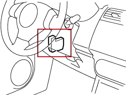
The fuse box is located under the dashboard on the left side.
| Diagram | ||
|---|---|---|
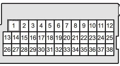
|
||
| No. | Protected Circuit | Rating (A) |
| 1 | Power windows (P/W) | 30 A |
| 2 | Instrument cluster (MTR) | 10 A |
| 3 | Ignition system (IG) | 15 A |
| 4 | Electronic power steering (IG1 SIG2) | 5 A |
| 5 | Not used (SHIFT) | 20 A |
| 6 | Power sunroof (S/R) | 20 A |
| 7 | Not used | — |
| 8 | Power door locks (D/L) | 20 A |
| 9 | Electronic steering lock (STL) | 15 A |
| 10 | Hazard warning lights (HAZ) | 10 A |
| 11 | Engine control module / Auto Start-Stop system (A-STOP) | 5 A |
| 12 | Rear fog lights (RR FOG) | 10 A |
| 13 | ABS/ESP control module (ABS) | 5 A |
| 14 | Heated seats (S/H) | 15 A |
| 15 | Camera / Advanced Driver Assistance Systems (ADAS) (IG1 SIG3) | 5 A |
| 16 | Interior dome light (DOME2) | 10 A |
| 17 | Instrument cluster illumination (DOME) | 5 A |
| 18 | Audio system / Radio (RADIO) | 15 A |
| 19 | Body Control Module (BCM) (CONT) | 5 A |
| 20 | Ignition switch / Keyless entry (KEY2) | 5 A |
| 21 | Power window timer (P/WT) | 20 A |
| 22 | Ignition switch (KEY) | 5 A |
| 23 | Horn (HORN) | 15 A |
| 24 | Left parking lights with automatic light control (TAIL) | 5 A |
| 25 | Parking lights: L+R without automatic light control / R with automatic light control (TAIL) | 10 A |
| 26 | SRS Airbags (A/B) | 10 A |
| 27 | BCM / Auto Start-Stop system (IG1 SIG) | 10 A |
| 28 | Reverse lights / Illumination (BACK) | 10 A |
| 29 | Accessory (ACC3) | 5 A |
| 30 | Rear window defogger (RR DEF) | 20 A |
| 31 | Heated outside mirrors (MRR HTR) | 10 A |
| 32 | 12 V power outlet / Cigarette lighter (ACC2) | 15 A |
| 33 | Audio system power (ACC) | 5 A |
| 34 | Rear window wiper (WIP) | 10 A |
| 35 | Blower motor relay (IG2 SIG) | 5 A |
| 36 | Windshield washer pump (WASH) | 15 A |
| 37 | Windshield wipers (FR WIP) | 25 A |
| 38 | Brake lights (STOP) | 10 A |
Engine Compartment
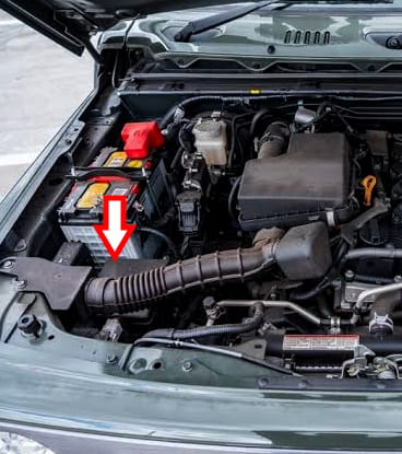
The fuse and relay box is located next to the battery behind a protective cover.
| Diagram | ||
|---|---|---|
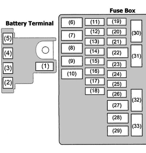
|
||
| No. | Protected Circuit | Rating (A) |
| 1 | Main power fuse (FL1) | 120 A |
| 2 | Power circuit (FL2) | 100 A |
| 3 | Power circuit (FL3) | 80 A |
| 4 | Power circuit (FL4) | 100 A |
| 5 | Power circuit (FL5) | 50 A |
| 6 | Ignition switch (main circuit) | 50 A |
| 7 | ABS pump motor | 40 A |
| 8 | Not used | — |
| 9 | Blower motor | 30 A |
| 10 | Starter solenoid (power circuit) | 30 A |
| 11 | Headlight washer | 30 A |
| 12 | Low/high beam headlight (right) | 15 A |
| 13 | Low/high beam headlight (left) | 15 A |
| 14 | ABS/ESP control module | 25 A |
| 15 | Not used | — |
| 16 | Ignition coils | 15 A |
| 17 | High beam headlight (main relay) | 25 A |
| 18 | Reverse light relay | 30 A |
| 19 | Not used | — |
| 20 | Fuel injection system | 15 A |
| 21 | Transmission control module (AT) | 15 A |
| 22 | Ignition switch (IG2) | 50 A |
| 23 | A/C compressor | 10 A |
| 24 | 4WD control module | 10 A |
| 25 | Front fog lights | 20 A |
| 26 | Not used | — |
| 27 | Electronic power steering | 40 A |
| 28 | Not used | — |
| 29 | Radiator cooling fan | 40 A |
| 30 | Not used | — |
| 31 | Starter relay control circuit | 5 A |
| 32 | High beam headlight (left) | 15 A |
| 33 | High beam headlight (right) | 15 A |
| Relay Modules | ||
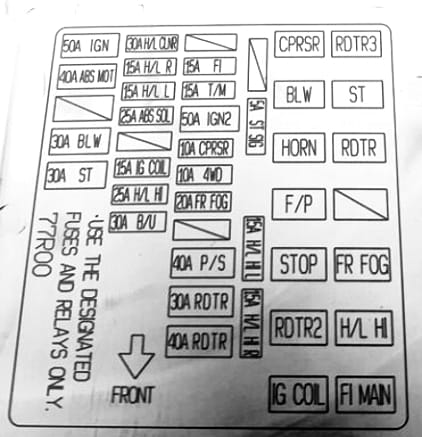
|
||
| ST | Starter relay | — |
| RDTR | Radiator fan relay | — |
| HORN | Horn relay | — |
| F/P | Fuel pump relay | — |
