
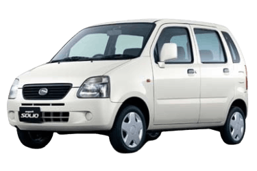
The Suzuki Wagon R has been produced from 1993 to the present across 6 generations in both left- and right-hand drive configurations and is distributed worldwide. It is one of the most popular Kei cars (Suzuki Kei). The slightly larger Suzuki Solio hatchback was built on this model's platform. This guide provides descriptions, diagrams, and photographic examples for the fuse and relay boxes of the Suzuki Wagon R / Solio (chassis codes MA / MB) produced from 1997 through 2008. The cigarette lighter fuse is highlighted in bold.
The exact wiring diagrams and component assignments for your specific Suzuki Wagon R are printed on the underside of the fuse box cover.
Engine Compartment
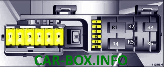
Main Fuse Box
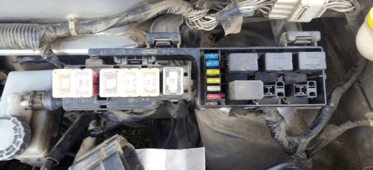
Located on the left side, directly behind the battery.
| Diagram | |
|---|---|
|
|
| No. | Description |
| 1 | 60 A – ABS module |
| 2 | 30 A – Cooling fan |
| 3 | 30 A – Electric Power Steering (EPS) |
| 4 | 60 A – Starter motor |
| 5 | 60 A – Exterior lighting, engine electronics, infotainment system |
| 6 | 80 A – Alternator (petrol engine) |
| 7 | 15 A – Low beam / high beam (right headlight) |
| 8 | 15 A – Instrument cluster, warning indicators, low beam / high beam (left headlight) |
| 9 | 20 A / 30 A – Radiator fan, electronic fuel injection (petrol engine) |
| 10 | 15 A – Front fog lamps |
| 11 | 15 A – Horn |
| 12 | Spare |
| R1 | Horn relay |
| R2 | Radiator fan relay |
| R3 | Fuel pump relay |
| R4 | Engine Control Module (ECM) / Ignition relay |
| R5 | Spare |
| R6 | Front fog lamp relay |
Auxiliary Fuse Box

A small secondary fuse block may be located above the battery. It contains fuses and glow plug preheating relays on applicable models.
Passenger Compartment

Located beneath the dashboard on the driver's side, behind the access panel.
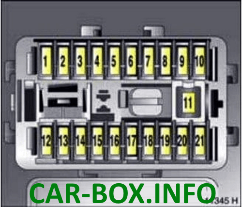
Type 1
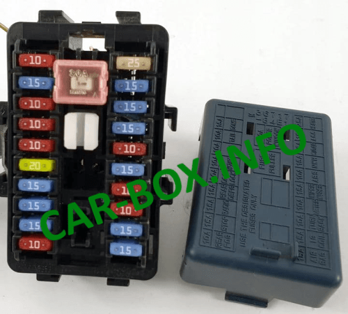
General view.
| Diagram | |
|---|---|
|
|
| No. | Description |
| 1 | 10 A – Front fog lamps |
| 2 | 15 A – Stop lamps |
| 3 | 15 A – Immobiliser system, infotainment, interior lighting |
| 4 | 15 A – Heated rear window |
| 5 | 20 A – Central locking system |
| 6 | 10 A – Alarm siren |
| 7 | 10 A – Air conditioning compressor clutch |
| 8 | 10 A – Tail lamps |
| 9 | 15 A – Interior dome lamps |
| 10 | 15 A – Central locking, instrument cluster, power mirrors |
| 11 | 30 A – Power windows |
| 12 | 15 A – Supplemental Restraint System (Airbags) |
| 13 | 15 A – Anti-theft system, Electric Power Steering (EPS), instrument cluster, climate control |
| 14 | 10 A – Central locking, turn signals, reversing lamps, headlight leveling system |
| 15 | 10 A – Speedometer and auxiliary instrumentation |
| 16 | 15 A – Windscreen wipers and washer system |
| 17 | 10 A – ABS module |
| 18 | 15 A – Engine Control Module (ECM) |
| 19 | 15 A – Cigarette lighter socket / power outlet |
| 20 | 15 A – Central locking, power mirrors, infotainment, instrument cluster, status indicators, cigarette lighter socket |
| 21 | 25 A – Blower motor, rear window defogger, air conditioning system |
Type 2
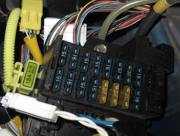
General view.
| Diagram | |
|---|---|

|
|
| 15 A – AIR BAG – Airbag system (SRS) 15 A – RADIO – Audio / Infotainment system 20 A – DOOR LOCK – Central door locking system 20 A – CIGAR – Cigarette lighter fuse 20 A – SUN ROOF – Power sunroof 15 A – TURN BACK – Reversing lamps / Turn signals 15 A – IG METER – Ignition circuit / Instrument cluster 15 A – H / L LH – Left headlight (Low/High beam) 15 A – FOG LAMP – Front fog lamps 15 A – FI – Fuel injection system 30 A – POWER STEERING – Electric Power Steering (EPS) 15 A – HEATER – Climate control / Blower motor 15 A – REAR DEFOG – Rear window defogger 15 A – TAIL STOP – Tail lamps, brake lamps 15 A – WASHER – Windscreen washer and wiper system 15 A – HORN – Horn 15 A – H / L RH – Right headlight (Low/High beam) |
