
The Suzuki Swift subcompact car has been produced across multiple generations since 1984. The first generation was not officially distributed in Europe and is omitted from this manual. The second generation was manufactured from 2002 through 2010, followed by the third generation produced from 2011 to 2020. This guide provides a detailed overview of Suzuki Swift (chassis codes ZC, ZD) fuse box and relay locations, circuit diagrams, and photographs, with specific callouts for the cigarette lighter and auxiliary power outlet fuses.
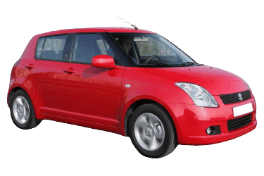
Fuse and relay assignments may vary depending on the vehicle's model year, trim level, and regional market specification. Always refer to the circuit decal on the inside of the fuse box cover.
Engine Compartment

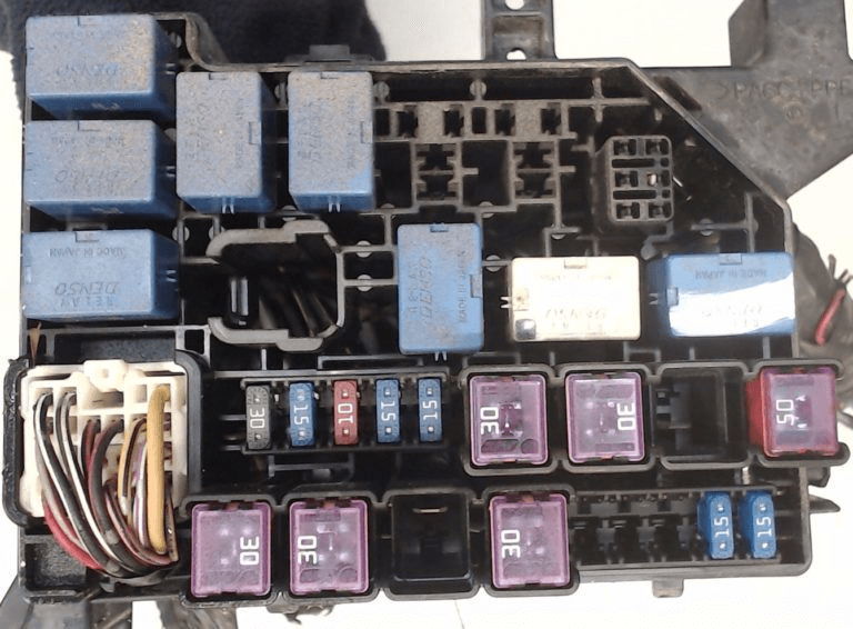
The engine compartment fuse box is located on the left side, adjacent to the shock strut tower.
Type 1
Diagram & Photo.
|
|

|
|
| No. | Circuit Protected |
| 1 | 80A Main fuse (All electrical circuits) |
| 2 | 50A Power windows, ignition switch, starter, windshield wipers |
| 3 | Tail lamps, rear window defogger, central locking system, horn, interior lighting |
| 4 | Radiator fan relay No. 1 |
| 5 | Radiator fan relay No. 2 |
| 6 | Radiator fan relay No. 3 |
| 7 | Starter relay |
| 8 | Main relay |
| 9 | Throttle body relay |
| 10 | Front fog lamp relay |
| 11 | Fuel pump relay |
| 12 | A/C compressor relay |
| 13 | Spare |
| 14 | 30A Blower motor / HVAC |
| 15 | 15A Fuel injection system (FI) |
| 16 | 10A A/C compressor clutch |
| 17 | Spare |
| 18 | 15A Stop lamps (Brake lights) |
| 19 | 30A ABS system |
| 20 | 30A Starter motor |
| 21 | Spare |
| 22 | 50A Electric power steering (EPS) |
| 23 | 30A Ignition switch |
| 24 | 30A Radiator cooling fan |
| 25 | Spare |
| 26 | 30A ABS system |
| 27 | Spare |
| 28 | Spare |
| 29 | 15A Front fog lamps |
| 30 | 15A Left headlight |
| 31 | 15A Right headlight |
| 32 | 80A Blower motor, electric power steering (EPS) |
| 33 | 80A Radiator fan, fog lamps, headlights |
Type 2
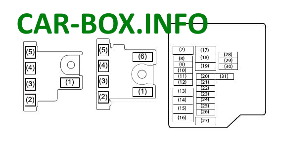
Diagram & Photo.

|
|
|
|
| No. | Circuit Protected |
| 1 | 100A / 120A Fusible link 1 (FL1) |
| 2 | 100A Fusible link 2 (FL2) |
| 3 | 100A Fusible link 3 (FL3) |
| 4 | 50A Fusible link 4 (FL4) |
| 5 | 80A Fusible link 5 (FL5) |
| 6 | 100A Fusible link 6 (FL6) |
| 7 | 50A Ignition switch 2 |
| 8 | 7.5A Engine Control Module (ECM) |
| 9 | Spare |
| 10 | 20A Fuel pump (Diesel) |
| 11 | 10A A/C compressor |
| 12 | 15A Fuel injection (Petrol) |
| 13 | 30A Fuel injection (Diesel) |
| 14 | 60A Electric power steering (EPS) |
| 15 | 30A Radiator cooling fan |
| 16 | 40A ABS pump motor |
| 17 | 30A Blower fan |
| 18 | 30A Starter motor |
| 19 | Spare |
| 20 | 30A Accessory power |
| 21 | Spare |
| 22 | 15A Left headlight |
| 23 | 25A ABS control module |
| 24 | 15A Right headlight |
| 25 | 20A Front fog lamps |
| 26 | Spare |
| 27 | 40A Ignition switch |
| 28 | 20A Engine control unit / Ignition coils |
| 29 | 10A Fuel injection 2 (Diesel) |
| 30 | Spare |
| 31 | 7.5A Starter signal |
Passenger Compartment
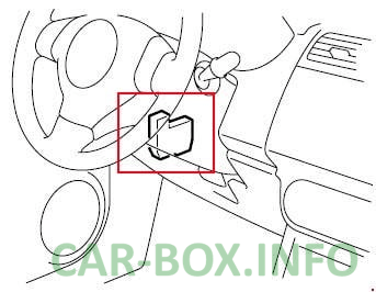
The cabin fuse box is located under the driver's side of the instrument panel, near the A-pillar.
Type 1
Diagram & Photo.
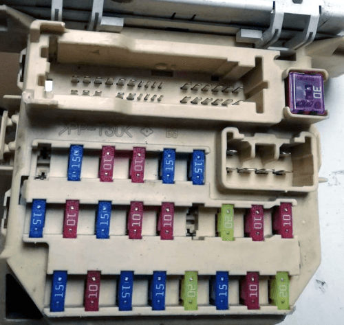
|
|
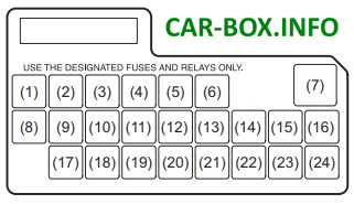
|
|
| No. | Circuit Protected |
| 1 | 15A Spare |
| 2 | 10A Ignition coil |
| 3 | 10A Backup lamps (Reverse lights) |
| 4 | 15A Instrument cluster (Combination meter) |
| 5 | 15A Power side mirrors |
| 6 | 15A Cigarette lighter / Auxiliary power socket |
| 7 | 15A Power windows |
| 8 | 15A Windshield wipers and washer |
| 9 | 10A Electric power steering (EPS) |
| 10 | 15A Supplemental Restraint System (SRS / Airbag) |
| 11 | 10A ABS control module |
| 12 | 10A Parking lamps / Side marker lights |
| 13 | Blank |
| 14 | 20A Power door locks |
| 15 | 10A Left headlight |
| 16 | 10A Starter signal |
| 17 | 15A Heated front seats |
| 18 | 10A HVAC / Blower control |
| 19 | 15A Rear fog lamps |
| 20 | 15A Audio system, interior lighting |
| 21 | 20A Rear window defogger |
| 22 | 15A Horn |
| 23 | 10A Right headlight |
| 24 | 20A Power window delay timer |
Type 2
Diagram & Photo.
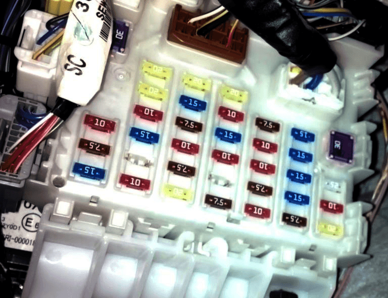
|
|
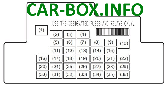
|
|
| No. | Circuit Protected |
| 1 | 30A Seat belt pretensioners |
| 2 | 20A Power window timer |
| 3 | 15A Electronic steering column lock |
| 4 | 20A Rear window defogger |
| 5 | 20A Sunroof / Moonroof |
| 6 | 10A Daytime running lights (DRL) |
| 7 | 10A Heated side mirrors |
| 8 | 7.5A Starter signal |
| 9 | 15A Auxiliary power socket 2 |
| 10 | 30A Power windows |
| 11 | 10A Security alarm siren |
| 12 | 7.5A Body Control Module (BCM) |
| 13 | 15A Ignition coil |
| 14 | 10A ABS control module |
| 15 | 15A Cigarette lighter socket |
| 16 | 10A Auto Stop-Start system controller |
| 17 | 15A Warning buzzer |
| 18 | 10A Stop lamps (Brake lights) |
| 19 | 10A Airbag system (SRS) |
| 20 | 10A Backup lamps (Reverse lights) |
| 21 | 15A Windshield washer |
| 22 | 30A Front wipers |
| 23 | 10A Dome light / Interior light |
| 24 | 15A All-Wheel Drive (4WD) control |
| 25 | 7.5A Rear fog lamps |
| 26 | Spare |
| 27 | 7.5A Ignition signal 1 |
| 28 | 15A Audio system 2 |
| 29 | 10A Auxiliary power socket 3 |
| 30 | 15A Audio system |
| 31 | 10A Tail lamps |
| 32 | 20A Door locks (D/L) |
| 33 | 7.5A Cruise control module |
| 34 | 10A Instrument cluster |
| 35 | 7.5A Ignition signal 2 |
| 36 | 20A Heated seats |
