
This guide covers the fuse and relay box diagrams and locations for the third-generation Suzuki Grand Vitara (chassis code JT; model years 2005, 2006, 2007, 2008, 2009, 2010, 2011, 2012, 2013, and 2014). It details the location of each fuse box, circuit diagrams, and reference photos. The fuse responsible for the cigarette lighter is highlighted in bold.
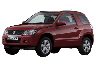
The layout and number of fuses or relays in your Suzuki Grand Vitara may vary depending on the model year and vehicle trim level.
In the Engine Compartment
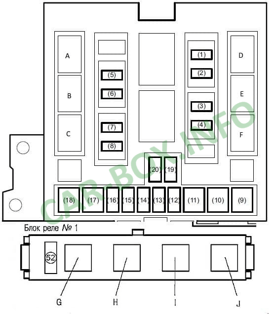
Main Fuse Box
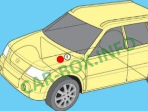
Located on the left side of the engine compartment near the strut tower, protected by a plastic cover.
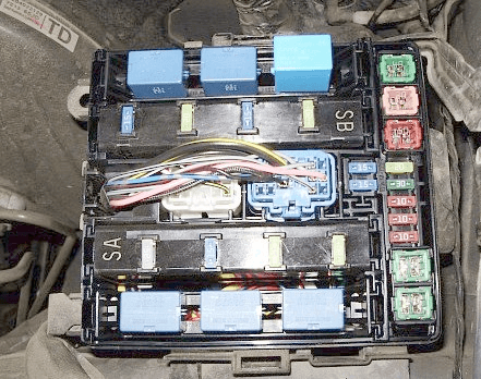
Reference photo.
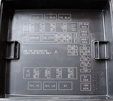
The specific fuse and relay layout diagram is printed on the inside of the cover.
| Diagram | |
|---|---|
|
|
| No. | Description |
| 1 | 15A Air conditioning (A/C) clutch |
| 2 | 20A Heated oxygen sensor (HO2S) |
| 3 | 15A Electronic throttle control |
| 4 | 20A Automatic transmission (A/T) |
| 5 | 25A Rear window defogger |
| 6 | 15A Horn |
| 7 | 20A Front fog lights |
| 8 | 20A Heated power mirrors |
| 19 | 15A Left headlight (low beam / HID), low beam relay |
| 20 | 15A Right headlight (low beam / HID), low beam relay |
| 9 | 40A Blower motor / Heater fan |
| 10 | 30A ABS / ESP control module 2 |
| 11 | 50A ABS / ESP control module 1 |
| 12 | 20A Main relay |
| 13 | 30A Headlight washer pump |
| 14 | 10A Left headlight (high beam) |
| 15 | 10A Right headlight (high beam) |
| 16 | 10A High beam relay, low beam relay |
| 17 | 40A Starter motor (ST) |
| 18 | 40A Ignition switch (IGN) |
| A | High beam relay |
| B | Low beam relay |
| C | Starter relay |
| D | Fuel pump relay |
| E | Main relay |
| F | Blower motor relay |
| G | Electronic throttle control relay |
| H | Radiator cooling fan relays No. 1, 2, 3 |
| I | |
| J | |
| K | Brake light relay |
Auxiliary Power Distribution Box
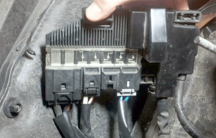
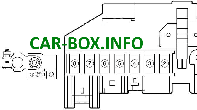
Located near the battery, this box houses high-current power fuses.
| Diagram | |
|---|---|
|
|
| No. | Circuit / Protected Components |
| 1 | 120A / 80A Main battery supply, engine fuse box No. 1 |
| 2 | 30A / 40A Radiator cooling fan relays No. 1 and No. 2 |
| 3 | Empty |
| 4 | 40A 4WD control module |
| 5 | 50A Ignition switch |
| 6 | 60A Passenger compartment fuse box No. 2, low beam relay, power distribution box |
| 7 | Integrated relay box No. 1, integrated relay box No. 2, passenger compartment fuse box No. 2 |
| 8 | Passenger compartment fuse box No. 2 |
In the Passenger Compartment

Mounted on the driver-side lower A-pillar / kick panel, under the dashboard.
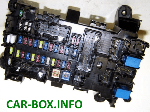
The exact layout diagram is printed on the inside of the fuse cover.
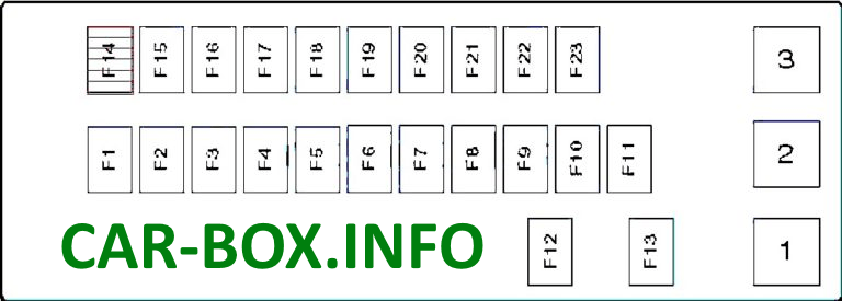
|
|
| No. | Description |
| 1 | Tailgate / Rear hatch relay |
| 2 | Auxiliary ignition circuit relay (ACC) |
| 3 | Shift interlock solenoid relay ("Park" position) |
| F1 | (20A) Alternator, ignition coils, Engine Control Module (ECM) |
| F2 | (10A) ECM, instrument cluster |
| F3 | (15A) Body Control Module (BCM), display unit, audio system |
| F4 | (20A) Central door locking system |
| F5 | (10A) Tail lamps / Rear clearance lights |
| F6 | (15A) Interior dome lights |
| F7 | (25A) Sunroof / Moonroof |
| F8 | (20A) Engine Control Module (ECM) |
| F9 | (7.5A) Starter control system |
| F10 | (15A) Hazard warning lights, turn signal flasher relay |
| F11 | (7.5A) Vanity mirror lights |
| F12 | (30A) Power windows |
| F13 | (20A) Power windows |
| F14 | (15A) Airbag system (SRS) |
| F15 | (10A) ABS / ESP control module, steering angle sensor |
| F16 | (10A) Reverse lights, transmission range sensor, headlight leveling switch |
| F17 | (15A) Radiator cooling fan relays No. 1, No. 2, and No. 3 |
| F18 | (20A) Windshield wipers |
| F19 | (15A) Cigarette lighter, power outlet |
| F20 | (10A) Cruise control, brake light switch |
| F21 | (15A) Auxiliary power outlet |
| F22 | (7.5A) Rear fog lights, combination switch |
| F23 | (15A) Stop / Brake lights |
Fuse No. 19 (15A) controls the front cigarette lighter, while fuse No. 21 (15A) powers the auxiliary 12V power sockets.
