Mini crossover Suzuki SX4 is produced in 3 generations from 2006 to the present with hatchback and sedan bodies. 1st generation was collected in 2007, 2008, 2009, 2010, 2011, 2012. 2nd generation in 2013, 2014 and 2015. Since 2016, the third generation of Suzuki SX4 has been supplied to the markets (2017, 2018, 2019, 2020, 2021). Although some consider it a restyled version of the second generation ( Suzuki New SX4 / S-Cross SX4) . Since the update mainly affected only the appearance of the SX4. In this publication you will find a description of the Suzuki CX4 fuse boxes and relays. We will also show block diagrams, photographs and their locations. The fuse responsible for the “Cigarette lighter” is highlighted in bold.

The design of the blocks depends on the year of manufacture, and the purpose of the elements depends on the level of equipment, the type of car body and the country of delivery.
In the engine compartment
It is located on the left side, next to the stand, under the protective cover.
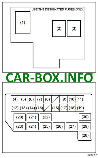
Type 1
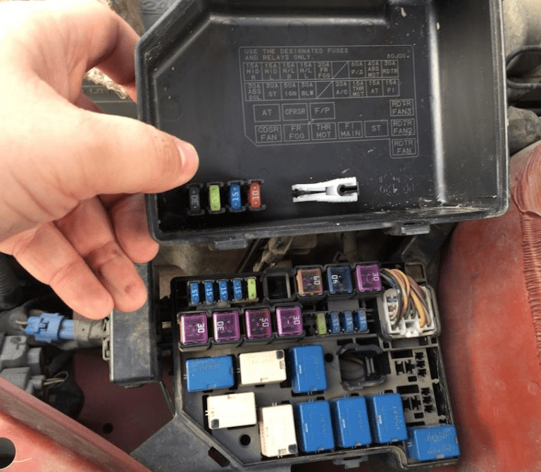
General view.
| Diagram | |
|---|---|
|
|
| № | Legend |
| 1 | 80A All electrical circuits |
| 2 | 50A Window regulator, ignition, wiper, starter |
| 3 | 50A Rear marker lamps, rear window heater, door lock, signal, interior lighting |
| 4 | Spare |
| 5 | Spare |
| 6 | 15A Headlamp (right side) |
| 7 | 15A Headlamp (left side) |
| 8 | 20A Fog lamps |
| 9 | 60A Power steering control unit |
| 10 | 40A ABS control unit |
| 11 | 30A radiator fan |
| 12 | 30A ABS control unit |
| 13 | 30A Starter |
| 14 | 50A Ignition lock |
| 15 | 30A Radiator Fan |
| 16 | 20A A / C Compressor |
| 17 | 15A Throttle valve motor |
| 18 | 15A Automatic transmission control module |
| 19 | 15A Injector |
| 20 | Automatic transmission relay |
| 21 | Air compressor relay |
| 22 | Fuel pump relay |
| 23 | Air conditioner fan relay |
| 24 | Fog lamp relay |
| 25 | Throttle valve relay |
| 26 | Main relay |
| 27 | Starter relay |
| 28 | Radiator fan relay |
| 29 | Radiator fan relay 2 |
| 30 | Radiator fan relay 3 |
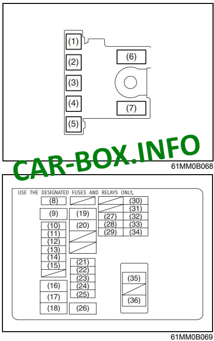
Type 2
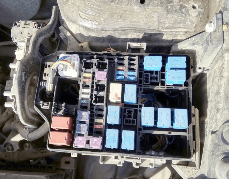
General view.
| Diagram | |
|---|---|
|
|
| № | Description |
| 1 | 50 / 60A FL7 |
| 2 | 50 / 80A FL6 |
| 3 | 100A FL5 |
| 4 | 80A FL4 |
| 5 | 100A FL3 |
| 6 | 60 / 100A FL2 |
| 7 | 100 / 120A FL1 |
| 8 | 7,5A Ignition - 1st signal (2) |
| 9 | 30A Radiator fan (2) |
| 10 | 20A Front fog lamps |
| 11 | 7,5A Headlight 2 |
| 12 | 30A Headlight washer |
| 13 | 25A ESP control module |
| 14 | 25A Headamps |
| 15 | 30A Accessories |
| 16 | 40A Ignition lock |
| 17 | 40A ESP® Engine |
| 18 | 30A Starter |
| 19 | 30A Fuel heater |
| 20 | 20A radiator fan |
| 21 | 30A DCDC |
| 22 | 30A Fl main (diesel engine) |
| 23 | 20A Fl (gasoline engine), Fuel pump (diesel engine) |
| 24 | 10A Air Compressor |
| 25 | 15A Continuously Variable Transmission (CVT) |
| 26 | 30A Heater fan |
| 27 | 7.5A Start signal |
| 28 | 15A Headlight (left) |
| 29 | 15A Upper headlight (left) |
| 30 | 7.5A FI 2 |
| 31 | 20A Engine management \ injection system |
| 32 | 15А FI |
| 33 | 15A Headlight (right) |
| 34 | 15A Upper headlight (right) |
| 35 | 50A Ignition lock 2 (diesel engine) |
| 36 | 50A Battery (diesel engine) |
In the passenger compartment
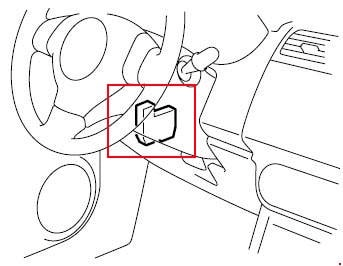
Fuse box attaches to the left pillar, under the dashboard on the driver's side.
Type 1
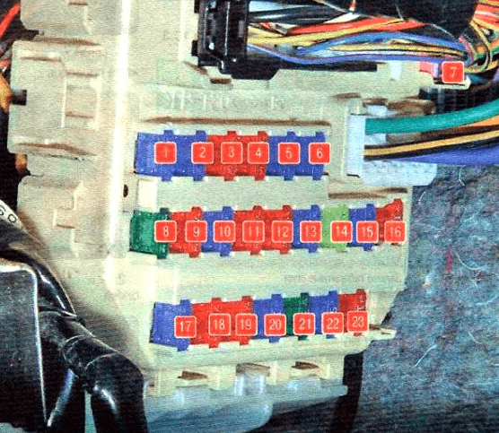
Diagram.
| № | Legend |
| 1 | 15A Rear door wiper |
| 2 | 15A Ignition system |
| 3 | 10A Reversing lamps |
| 4 | 10A Instrument panel |
| 5 | 15A Cigarette lighter and additional consumers |
| 6 | 15A Cigarette lighter and additional consumers |
| 7 | 15A Power Windows |
| 8 | 30A Windshield wiper |
| 9 | 10A Electric power steering |
| 10 | 15A Airbags |
| 11 | 10A Anti-lock braking system |
| 12 | 10A Rear parking lights |
| 13 | 15A Stop lamps |
| 14 | 20A Door locks |
| 15 | 15A Spare |
| 16 | 10A Starter |
| 17 | 15A Heated seats |
| 18 | 10A A / C fan relay |
| 19 | 10A Rear fog lamps |
| 20 | 15A Interior lighting plafond |
| 21 | 30A Heated rear window |
| 22 | 15A Horn, Siren |
| 23 | 10A Immobilizer 20A Power windows |
| 24 | 30A Heated rear window |
| For the operation of the cigarette lighter and additional sockets, fuses number 5 and 6 at 15A are responsible. | |
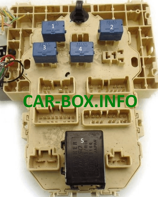
| Several relay elements can be located on the back of the unit: | |
|
|
| 1 - Air conditioner fan motor; 2 - Horn relay; 3 - Rear window cleaner; 4 - Heated rear window; 5 - Alarm relay |
|
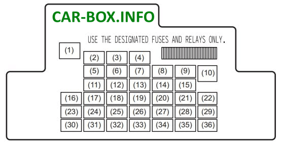
Type 2

Access example.
| Diagram | |
|---|---|
|
|
| № | Description |
| 1 | 30A seat belt |
| 2 | 20A Power Window Timer |
| 3 | 15A Steering column lock |
| 4 | 20A Heated rear window |
| 5 | 20A Hatch |
| 6 | 10A DRL |
| 7 | 10A Heated exterior mirrors |
| 8 | 7,5A Start signal |
| 9 | 15A Socket for additional equipment 2 |
| 10 | 30A Power window |
| 11 | 10A Alarm |
| 12 | 7.5A BCM |
| 13 | 15A Ignition coil |
| 14 | 10A ABS control module |
| 15 | 15A cigarette lighter socket |
| 16 | 10A Controller A-STOP |
| 17 | 15A Buzzer |
| 18 | 10A brake light |
| 19 | 10A Airbag |
| 20 | 10A Reversing light |
| 21 | 15A Cleaner / Washer |
| 22 | 30A Front wiper |
| 23 | 10A Ceiling light |
| 24 | 15A 4WD |
| 25 | 7,5A Rear fog lamps |
| 26 | Spare |
| 27 | 7,5A Ignition - 1st signal |
| 28 | 15A Radio 2 |
| 29 | 10A Socket for additional equipment 3 |
| 30 | 15A Radio |
| 31 | 10A Rear light |
| 32 | 20A D / L |
| 33 | 7,5A Cruise control |
| 34 | 10A Measuring instrument |
| 35 | 7,5A Ignition - 2nd signal |
| 36 | 20A Heated seats |
Fuse number 15 at 15A is responsible for the cigarette lighter, and for additional sockets numbers 9 and 29.
