The compact SUV Suzuki Jimny has been produced since 1968 with various changes and modifications to the present. In this publication, we will show a description of the Suzuki Jimny fuse and relay blocks produced in 1998, 1999, 2000, 2001, 2002, 2003, 2004, 2005, 2006, 2007, 2008, 2009, 2010, 2011, 2012, 2013, 2014, 2015, 2016 and 2017, their locations, photographs and diagrams. The fuse responsible for the “Cigarette lighter” is highlighted in bold.

The design of the blocks and the purpose of their elements may differ from the one presented and depend on the year of manufacture and equipment of your Suzuki Jimny. The current diagram will be printed on the block cover.
In the engine compartment
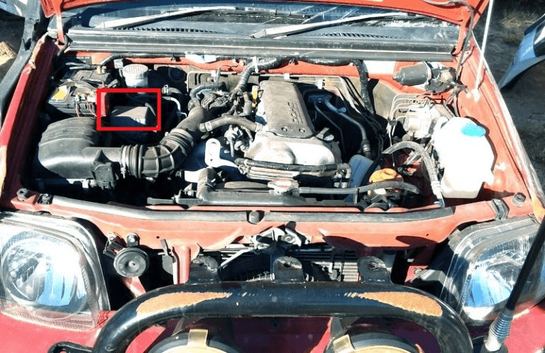
In a Suzuki Jimny with gasoline engines, it is on the left side, next to the battery. In diesel engines - on the right side.
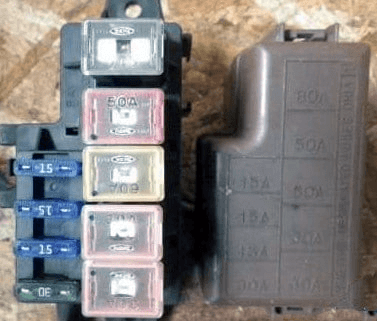
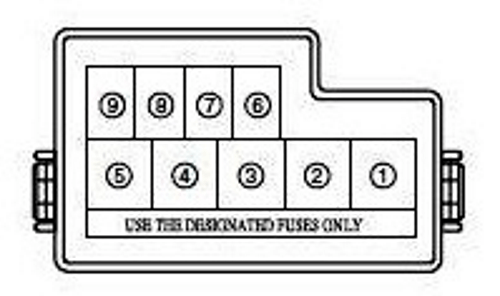
Type 1
Diagram & Photo
|
|
|
|
| № | Legend |
| 1 | 80A WATT (battery, generator) |
| 2 | 50A ABS (ABS module) |
| 3 | 60A IG (ignition switch) |
| 4 | 30A LAMP (lighting, etc. - the circuit of the distribution box in the cabin) |
| 5 | 30A LAMP (lighting, etc: - the circuit of the distribution box in the cabin) |
| 6 | 15A HEAD L (instrument cluster, left headlight) |
| 7 | 15A HEAD R (right headlight) |
| 8 | 15A F1 (main relay) |
| 9 | 15А А / С (relay and electric condenser fan) |
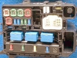
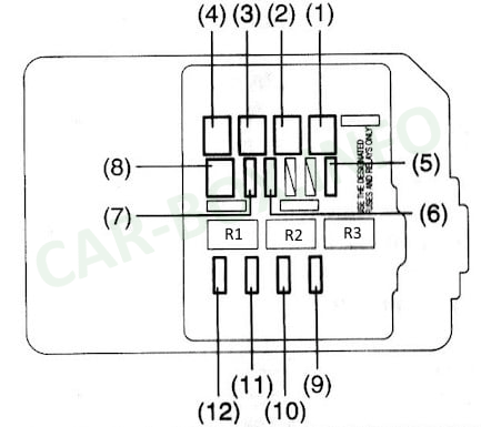
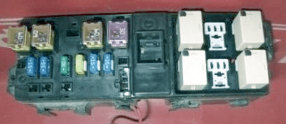
Type 2
Diagram & Photo
|
|
|
|
| № | Designations |
| 1 | 50A Ignition lock |
| 2 | 40A ABS motor |
| 3 | 40A Ignition lock |
| 4 | 30A Salenoid ABS |
| 5 | 15A Engine control system |
| 6 | 15A Left headlight |
| 7 | 15A Right headlight |
| 8 | 50A Passenger compartment fuse box |
| 9 | 15A Front fog lamps |
| 10 | 20A Fan |
| 11 | 30A Stranter |
| 12 | 20A Air conditioner |
| R1 | Fuel pump relay |
| R2 | Air conditioner condenser fan motor relay |
| R3 | Relay engine management system |
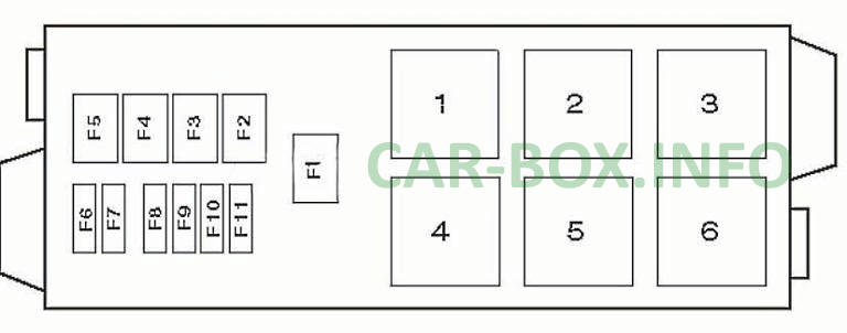
Type 3
Diagram & Photo
|
|
|
|
| № | Description |
| 1 | A / C compressor electromagnetic clutch relay |
| 2 | Empty |
| 3 | Empty |
| 4 | Coolant heater relay |
| 5 | Empty |
| 6 | Engine control relay |
| F1 | (80A) Generator |
| F2 | (30A) Cooling fan motor |
| F3 | (50A) ABS system |
| F4 | (60A) - |
| F5 | (60A) Ignition lock circuits |
| F6 | (15A) LH headlamp |
| F7 | (15A) RH headlamp |
| F8 | (20A) Heater blower motor |
| F9 | (30A) Starter |
| F10 | (30A) ECM |
| F11 | (15A) A / C compressor magnetic clutch |
In the passenger compartment
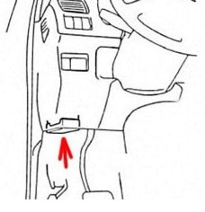
Located under the dashboard on the driver's side.
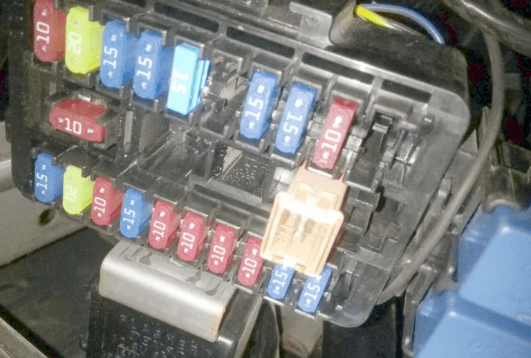
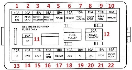
Type 1
Diagram & Photo
|
|
|
|
| № | Description |
| F1 | 10A Heater blower motor |
| F2 | 15A / 20A Heated rear window |
| F3 | 15A Cleaner, glass washer |
| F4 | 15A Heated seats |
| F5 | 15A Cigarette lighter fuse |
| F6 | 15A Heated windshield |
| F7 | 15A Siren |
| F8 | 15A Radio |
| F9 | 10A Rear fog lamp (s) |
| F10 | 10A Immobilizer |
| F11 | 10A Starter |
| F12 | 30A Power windows |
| F13 | 15A Engine management system |
| F14 | 20A 4WD control system |
| F15 | 10A Reversing lamp (s) |
| F16 | 15A SRS system |
| F17 | 10A Instrument panel |
| F18 | 10A ABS system |
| F19 | 10A Electronic gearbox control unit |
| F20 | 10A Rear tail lamps |
| F21 | 15A Stop lights |
| F22 | 15A Central locking |
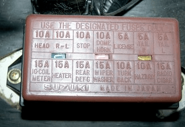
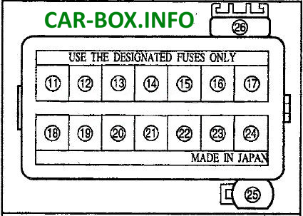
Type 2
Diagram & Photo
|
|
|
|
| Name | Legend |
| A / C | air conditioning |
| ABS | ABS |
| ALT | generator |
| ALT-S | generator |
| AM | engine switch |
| DEF | window heater |
| DOME | interior lighting |
| DOOR | power door |
| ECU | control (control) engine module |
| EDU | injection control |
| EFI | electronic injection control system |
| ENG MAIN | main engine |
| FAN | fan |
| FOG | fog lights |
| Fr | front |
| F-TAIL | taillights |
| GAUGE | dashboard, speedometer |
| HAZARD | alarms |
| HAZ-TRN | hazard warning lights - turns |
| HEAD | Headlamps |
| HEAD LH | Headlamps left |
| HEAD RH | Headlamps right |
| HORN | sound signal |
| HTR | heater |
| I / UP | idling |
| IG | ignition |
| IGN | ignition |
| MAIN | main |
| P / W | power window |
| POWER | power suply |
| PWR | power suply |
| RAD | radio |
| Rr | rear |
| SIG | cigarette lighter fuse |
| SPARE | spare |
| ST | starter |
| STOP | stop signal |
| TAIL | taillights |
| TURN | turn signals |
| WASH | windscreen washer |
| WIP | wiper |
| WIPER | wiper |
