The Toyota Prius is a groundbreaking hybrid technology car in 1997. According to the manufacturer, this is the first production car with an innovative combination of an internal combustion engine and an electric motor. The first years of production, the Prius was sold only in Japan, but with the appearance of an updated version in 2000, the sedan went on sale in foreign markets, including in Europe. There is no need to talk about a special variety of the model range - the car has one modification, equipped with a 1.5-liter inline four-cylinder engine with a capacity of 70 hp, which is combined with a 33-kilowatt electric motor.
The above diagrams are relevant for Toyota Prius 1st generation restyled (XW11) 2000, 2001, 2002, 2003 models.
In the passenger compartment
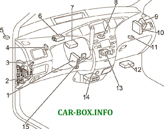
Location of components: 1. Brake control unit; 2. Control unit for body electrical equipment; 3. Fuse box; 4. Relay for daytime running lights; 5. Relay of direction indicators; 6. Key transponder; 7. Receiver for central locking; 8. Block of a network gateway; 9. Power steering control unit; 10. Engine control unit; 11. Relay for reversing lamps; 12. Hybrid system control unit; 13. Air conditioner amplifier; 14. Airbag control unit; 15. Control unit for blocking the gear selector
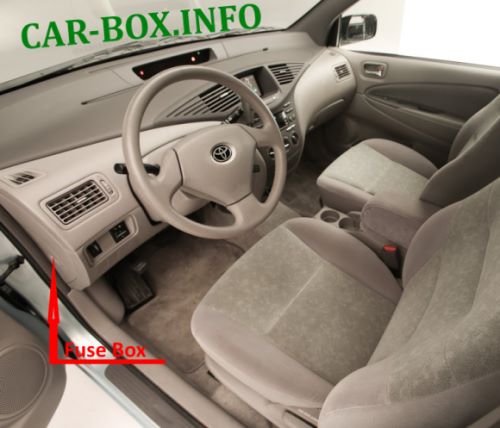
Photo location of the main block (LHD & RHD)

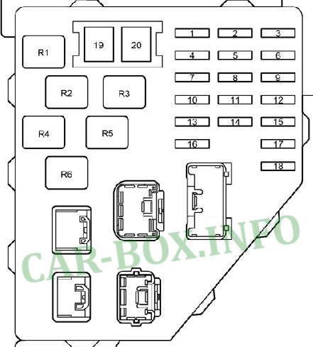
General view.
| Diagram | ||
|---|---|---|
|
||
| No. | Description | A |
| 1 | Audio system, ashtray lighting, headlight range control, hazard warning lights | 5 |
| 2 | Instrument cluster, alarm, heated rear window, service indicators, warning buzzer, reversing lamps, power windows, air conditioning | 10 |
| 3 | Air conditioning | 10 |
| 4 | Side lamps, license plate lamp | 7.5 |
| 5 | Air conditioning, ABS, power steering, daytime running lamps | 5 |
| 6 | Brake lamps, auxiliary brake lamp, ABS | 15 |
| 7 | ABS indicator, clock, audio system, multi-information display, gear selector lock | 10 |
| 8 | Wiper | 30 |
| 9 | Air conditioning, daytime running lights, power steering, immobilizer | 7.5 |
| 10 | Socket (cigarette lighter) | 15 |
| 11 | Glass washer | 15 |
| 12 | central locking | 30 |
| 13 | Airbags, seat belt pretensioner | 10 |
| 14 | Empty | - |
| 15 | Diagnostic connector | 7.5 |
| 16 | Empty | - |
| 17 | power windows | 20 |
| 18 | Fuses: "ACC", "CIG", "SRS ACC", "WASHER", "HTR", "WIPER", "ECU-IG", "GAUGE" | 5 |
| 19 | Heated rear window | 40 |
| 20 | Window lifters | 30 |
| Relay | ||
| R1 | Ignition (IG1) | |
| R2 | Side lamps (TAIL) | |
| R3 | Auxiliary relay (ACC) | |
| R4 | Empty | |
| R5 | Power relay (power windows) | |
| R6 | Heated rear window (DEF) | |
In the engine compartment


Location of components: 1. Main box; 2. Additional fuse box; 3. Relay box
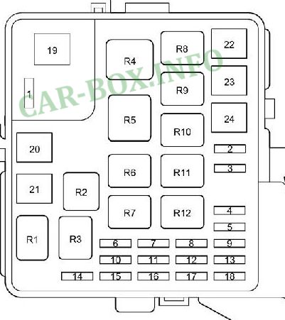
Fuse box #1
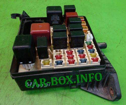
General view.
| Diagram | ||
|---|---|---|
|
||
| No. | Decoding | A |
| 1 | Empty | - |
| 2 | Empty | - |
| 3 | Empty | - |
| 4 | Air conditioning | 30 |
| 5 | Horn | 10 |
| 6 | Empty | - |
| 7 | Daytime running lamps: High beam right | 10 |
| 8 | Starting system, multiport fuel injection system / sequential multiport fuel injection system, immobilizer | 15 |
| 9 | Throttle valve | 15 |
| 10 | Right headlamp | 10 |
| Daytime running lamps: Low beam right | 10 | |
| 11 | Daytime running lamps: High beam left | 10 |
| 12 | Battery fan | 10 |
| 13 | Brake booster | 20 |
| 14 | Hybrid system | 20 |
| 15 | Multiport fuel injection system / sequential multiport fuel injection system | 15 |
| 16 | Left headlamp | 10 |
| Daytime running lamps: Low beam left | 10 | |
| 17 | Audio system, multi-information display, interior lighting, luggage compartment lighting, power windows, wireless control system | 15 |
| 18 | Direction indicators. alarm | 10 |
| 19 | Fuses: ACC relay, IG1 relay, TAIL relay, "ABS NO.4", "HTR1", "HTR2", "ABS NO.1", "HTR3", "EMPS", "CDS FAN", "RDI", "HTR", OBD II "," ECU-B "," STOP "," PWR1 "," POWER "," DOOR "," DEF "," AM1 " | 100 |
| 20 | Daytime Running lamps | 30 |
| Without daytime running lamps: Jumper | - | |
| 21 | Empty | - |
| 22 | Air conditioning | 50 |
| 23 | Cooling fan | 30 |
| 24 | Brake booster | 30 |
| Relay | ||
| R1 | Daytime running lamps: Dimmer (DIM) | |
| Without daytime running lamps: Jumper | ||
| R2 | Headlamp (HEAD) | |
| R3 | Fuel pump (C / OPN) | |
| R4 | Heater (HTR) | |
| R5 | Daytime running lamps: Jumper | |
| R6 | Engine control unit (EFI) | |
| R7 | A / C Compressor Clutch (CLR MG) | |
| R8 | Cooling fan (FAN NO.1) | |
| R9 | Cooling fan (FAN NO.2) | |
| R10 | Cooling fan (FAN NO.3) | |
| R11 | Ignition (IG2) | |
| R12 | Horn | |
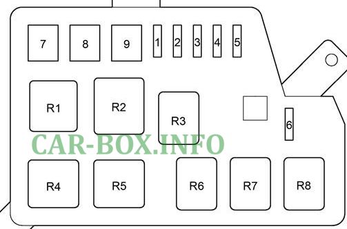
Additional fuse box #2
Diagram.
|
||
| No. | Appointment | A |
| 1 | ABS | 10 |
| 2 | Air conditioning | 30 |
| 3 | Empty | - |
| 4 | Air conditioning | 30 |
| 5 | Empty | - |
| 6 | Daytime Running Lamps | 7.5 |
| 7 | Air conditioning | 50 |
| 8 | Power steering | 50 |
| 9 | ABS | 40 |
| Relay | ||
| R1 | Daytime running Lamps(DRL) | |
| R2 | ABS (ABS SOL) | |
| R3 | (A / CW / P) | |
| R4 | Power steering (EMPS) | |
| R5 | Heater (HTR3) | |
| R6 | Empty | |
| R7 | Heater (HTR1) | |
| R8 | Heater (HTR2) | |
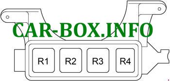
Relay box #3
Diagram.
|
|
| R1 | (HYDRO MTR NO.1) |
| R2 | (HYDRO MTR NO.2) |
| R3 | Empty |
| R4 | (IGCT) |
Car Body
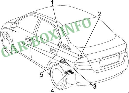
Location of components : 1. Navigation control unit; 2. Battery fan relay; 3. Battery control unit; 4. Power fuse box; 5 Main relay
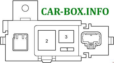
Power block #4
#4 on the picture.
| Diagram | ||
|---|---|---|
|
||
| No. | Appointment | A |
| 1 | Inverter and converter | 5 |
| 2 | MAIN Fuses: "DC / DC", "BATT FAN", "HORN", "TURN-HAZ", "DOME", "THRO", "EFI", "AM2", "ABS NO.2", "ABS NO .3 "," DC / DC-S "," HV "," HEAD " | 120 |
| 3 | Empty | - |
