
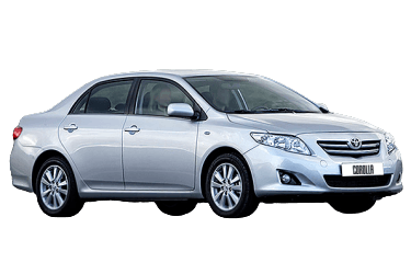
The Toyota Corolla E150 was produced from 2007 through 2013 and sold worldwide. During its production run, the model underwent a facelift. In certain markets, it is known as the Axio and Altis. This guide details the locations of the electronic control units (ECUs), as well as the fuse and relay boxes for the 150-series Corolla, complete with component layout diagrams, fuse assignments, and photos. The cigarette lighter fuse location is highlighted below.
Fuse box configurations and element assignments may vary depending on vehicle equipment and market. Always verify the fuse assignments against the diagram on the inside of the fuse box cover.
Engine Compartment
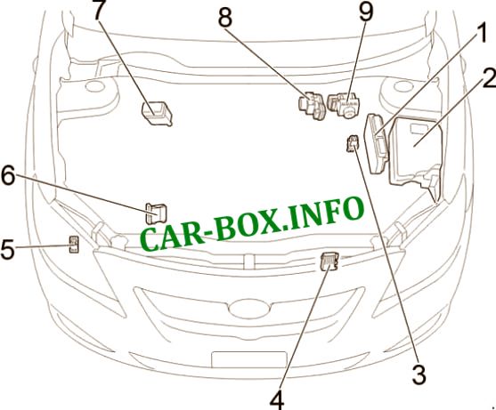
Component locations in the engine compartment:
1 - Engine Control Module (ECM);
2 - Main fuse and relay box;
3 - Glow plug relay;
4 - Cooling fan control module;
5 - LHD: Headlight washer relay;
6 - Injector driver module (EDU);
7 - Relay box;
8 - Gasoline: Brake control ECU / ABS module;
9 - Diesel: Brake control ECU / ABS module
Main fuse and relay box
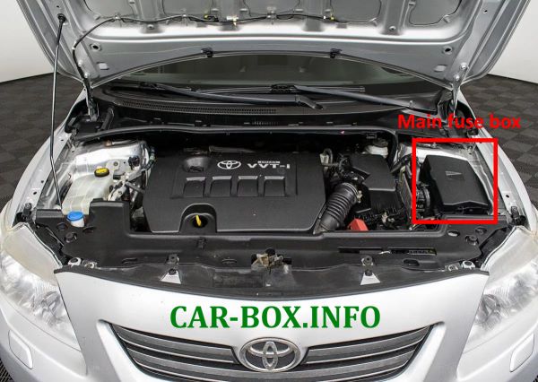
Located on the left side of the engine compartment, under the cowl panel.
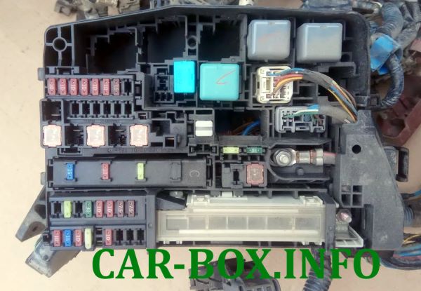
General view.
Type 1
Diagram.
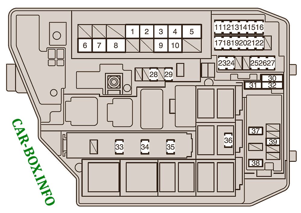
|
|
| No. | Rating / Circuit Protected |
| 1 | 30A CDS FAN - Electric cooling fan |
| 2 | 40A RDI FAN - Radiator cooling fan |
| 3 | 30A ABS NO. 3 - Anti-lock Brake System (ABS), Vehicle Stability Control (VSC) |
| 4 | 50A ABS NO. 1 - Anti-lock Brake System (ABS), Vehicle Stability Control (VSC) |
| 5 | 50A HTR - Air conditioning system |
| 6 | 120A ALT - Charging system, RDI FAN, CDS FAN, ABS NO. 1, ABS NO. 3, HTR, HTR SUB NO. 1, HTR SUB NO. 3, ACC, CIG, METER, IGN, ECU-IG NO. 2, HTR-IG, WIPER, WASHER, ECU-IG NO. 1, AM1, DOOR, STOP, FR DOOR, POWER, RL DOOR, RR DOOR, OBD, ACC-B, FR FOG, DEF, MIR HTR, REAR FOG, PANEL |
| 7 | 60A EPS - Electric Power Steering (EPS) |
| 8 | 80A GLOW - Glow plug system |
| 9 | 50A P / I - EFI MAIN, HORN, IG2 |
| 10 | 50A H-LP MAIN - Headlights |
| 11 | 10A EFI NO. 2 - Emission control system |
| 12 | 10A EFI NO. 1 - Multiport fuel injection system (SFI/MFI) |
| 13 | 10A H-LP RH HI - Right headlight (high beam) |
| 14 | 10A H-LP LH HI - Left headlight (high beam) |
| 15 | 10A H-LP RH LO - Right headlight (low beam) |
| 16 | 10A H-LP LH LO - Left headlight (low beam) |
| 17 | 10A ETCS - Electronic Throttle Control System (ETCS) |
| 18 | 10A TURN-HAZ - Turn signals, hazard warning lights |
| 19 | 7.5A ALT-S - Charging system |
| 20 | 7.5A AM2 NO. 2 - Multiport fuel injection system, starting system |
| 21 | 30A AM2 - Starting system / Starter |
| 22 | 20A STRG LOCK - Steering lock system |
| 23 | 7.5A IG2 NO. 2 - Starting system |
| 24 | 10A ECU-B2 - Air conditioning system |
| 25 | 10A ECU-B - Main Body ECU, instrument cluster and gauges |
| 26 | 15A RAD NO. 1 - Audio system |
| 27 | 10A DOME - Interior lighting, luggage compartment light, Smart Entry & Start system |
| 28 | 30A AMP - Audio amplifier |
| 29 | 10A MAYDAY - Emergency communication system |
| 30 | 10A SPARE |
| 31 | 30A SPARE |
| 32 | 20A SPARE |
| 33 | 20A EFI MAIN - Multiport fuel injection system, EFI NO. 1, EFI NO. 2 |
| 34 | 10A HORN - Horn |
| 35 | 15A IG2 - Multiport fuel injection system, starting system, IGN, METER |
| 36 | 7.5A ST - Starting system |
| 37 | 30A HTR SUB NO. 1 - Auxiliary PTC heater |
| 38 | 30A HTR SUB NO. 3 - Auxiliary PTC heater |
| 39 | 15A PWR OUTLET / INVERTER or PWR OUTLET - Power outlet, cigarette lighter |
Type 2
Diagram.
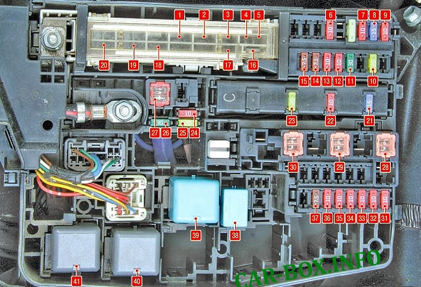
|
|
| No. | Rating / Circuit Protected |
| F1 | 30A H-LP CLN - Headlight washers |
| F2 | 45A RDI FAN - Radiator cooling fan |
| F3 | 30A ABS NO. 3 - ABS and VSC |
| F4 | 50A ABS NO. 1 - ABS and VSC |
| F5 | 50A HTR - Air conditioning system |
| F6 | 10A ECU-B2 - Automated Manual Transmission (MMT), air conditioning, Smart Entry & Start system |
| F7 | 10A ECU-B - Instrument cluster, Body Control Module (BCM), VSC, power door locks, power windows |
| F8 | 15A RAD NO. 1 - Audio system |
| F9 | 10A DOME - Interior lighting, luggage compartment light, Smart Entry & Start system |
| F10 | 20A STRG LOCK - Steering lock system |
| F11 | 30A AM2 - Engine starting system, Smart Entry & Start system, fuel injection system |
| F12 | 10A ETCS - Electronic Throttle Control System |
| F13 | 10A TURN-HAZ - Turn signals and hazard warning lights |
| F14 | 7.5A ALT-S - Charging system |
| F15 | 7.5A AM2 NO. 2 - Body Control Module (BCM) |
| F16 | 50A H-LP MAIN - Headlights |
| F17 | 50A P / I - Fuel injection system |
| F18 | 80A GLOW - Glow plug system (diesel engines) |
| F19 | 60A EPS - Electric Power Steering (EPS) |
| F20 | 120A ALT - Charging system |
| F21 | 15A IG2 - Fuel injection system, Smart Entry & Start system |
| F22 | 10A HORN - Horn |
| F23 | 20A EFI MAIN - Fuel injection system |
| F24 | Spare |
| F25 | Spare |
| F26 | Spare |
| F27 | 50A AMT - Automated Manual Transmission (MMT) |
| F28 | 30A HTR SUB NO. 3 - Auxiliary PTC heater |
| F29 | 30A HTR SUB NO. 2 - Auxiliary PTC heater |
| F30 | 30A HTR SUB NO. 1 - Auxiliary PTC heater |
| F31 | 10A H-LP LH LO - Left headlight (low beam) |
| F32 | 10A H-LP RH LO - Right headlight (low beam) |
| F33 | 10A H-LP LH HI - Left headlight (high beam) |
| F34 | 10A H-LP RH HI - Right headlight (high beam) |
| F35 | 10A EFI NO. 1 - Multiport fuel injection system |
| F36 | 10A EFI NO. 2 - Multiport fuel injection system |
| F37 | 7.5A IG2 NO. 2 - Starting system, Smart Entry & Start system |
| 38 | FR DEICER - Front windshield deicer relay |
| 39 | IGT / INJ - Ignition / Fuel injector relay |
| 40 | AMT - Automated Manual Transmission (MMT) relay |
| 41 | H-LP - Headlight relay |
| Auxiliary relay box | |
|---|---|
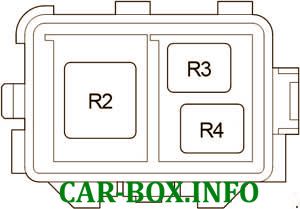
|
|
| No. | Description |
| R2 | Auxiliary heater (HTR SUB NO. 1) |
| R3 | Auxiliary heater (HTR SUB NO. 3) |
| R4 | Auxiliary heater (HTR SUB NO. 2) |
Passenger Compartment
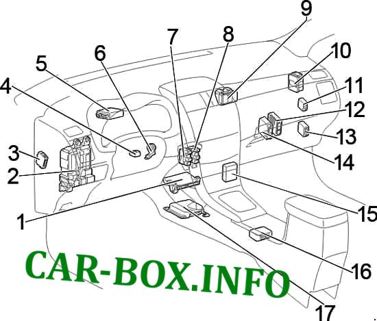
Component locations in the passenger compartment (Corolla E150):
1. Air conditioning control unit;
2. Fuse Box / Main Body ECU;
3. LHD: Headlight leveling control unit;
4. Steering lock control unit;
5. Power steering ECU;
6. Transponder key amplifier;
7. Relay box No. 1;
8. Relay box No. 2;
9. Junction block;
10. Junction block;
11. Windshield wiper relay;
12. LHD : Multi-Mode Manual Transmission (MMT) control unit;
13. Engine and Transmission Control Module (PCM / ECM);
14. Stop & Start system control unit;
15. Multimedia interface control unit;
16. LHD: Shift lock control unit;
17. Airbag sensor assembly / Airbag ECU;
18. RHD: Turn signal flasher relay
Main fuse box
Located on the lower left side of the instrument panel. Press the cover latch to access the fuses.
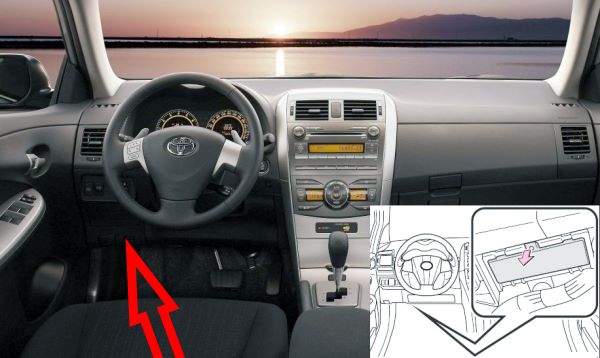
Left-Hand Drive (LHD).
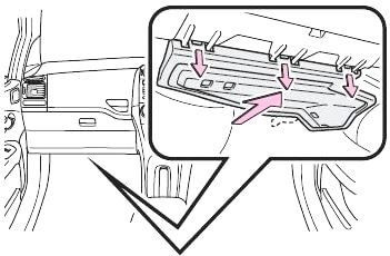
Right-Hand Drive (RHD).

Accessing the fuse box.
| Passenger Compartment Fuse Assignments | |
|---|---|
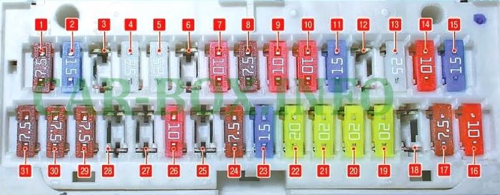
|
|
| No. | Rating - Description |
| 1 | 7.5A AM1 - Starter, multiport fuel injection system, “CIG” and “ACC” fuses |
| 2 | 15A FR FOG - Front fog lights |
| 3 | Empty |
| 4 | 25A ACC-B - “CIG” and “ACC” fuses |
| 5 | 25A DOOR - Power door lock system |
| 6 | Empty |
| 7 | 10A STOP - Stop lights, high-mount stop light, ABS, VSC, Body ECU, multiport fuel injection system, transmission control module |
| 8 | 7.5A OBD - On-Board Diagnostics (OBD) port |
| 9 | 10A ECU-IG NO. 2 - Reverse lights, charging system, auto-dimming rearview mirror, display monitor, moonroof, rear window defogger, air conditioning system, turn signals, hazard warning lights, front passenger seatbelt warning, Stop & Start system, parking assist system |
| 10 | 10A ECU-IG NO. 1 - Without Stop & Start system: Automatic headlight leveling, Body ECU, electric power steering, cooling fans, shift lock, rain sensor, ABS, VSC, audio system, navigation system, multiport fuel injection system, headlight washers, Smart Entry & Start system |
| 11 | 15A WASHER - Windshield washer |
| 12 | Empty |
| 13 | 25A WIPER - Windshield wipers, rain sensor |
| 14 | 10A HTR-IG - Air conditioning system, rear window defogger, auxiliary heater |
| 15 | 15A SEAT HTR - Seat heaters |
| 16 | 10A TAIL - Tail lights, license plate lights, rear fog lights, front fog lights, headlight leveling, multiport fuel injection system, instrument panel illumination |
| 17 | 7.5A PANEL - Headlight switch, instrument cluster illumination, glove box light, steering wheel switches, Body ECU |
| 18 | 10A ECU-IG NO. 1 - With Stop & Start system: Automatic headlight leveling, Body ECU, electric power steering, cooling fans, shift lock, rain sensor, ABS, VSC, audio system, navigation system, multiport fuel injection system, headlight washers, Smart Entry & Start system, Stop & Start system |
| 19 | 20A FR DOOR - Front right power window |
| 20 | 20A RL DOOR - Rear left power window |
| 21 | 20A RR DOOR - Rear right power window |
| 22 | 20A SUNROOF - Moonroof |
| 23 | 15A CIG - Cigarette lighter fuse |
| 24 | 7.5A ACC - Power mirrors, audio system, navigation system, shift lock, Body ECU, Smart Entry & Start system, Stop & Start system |
| 25 | Empty |
| 26 | 10A MIR HTR - Heated outside mirrors, multiport fuel injection system |
| 27 | Empty |
| 28 | Empty |
| 29 | 7.5A RR FOG - Rear fog lights |
| 30 | 7.5A IGN - Steering lock, SRS airbags, transmission control module, multiport fuel injection system, Smart Entry & Start system, Stop & Start system |
| 31 | 7.5A METER - Instrument cluster, Stop & Start system |
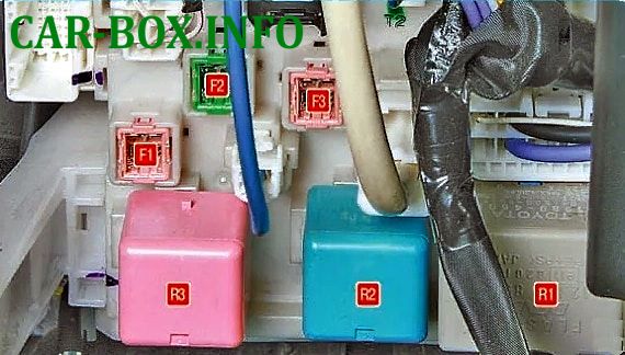
Upper section of the block

To gain access on LHD models, remove the lower instrument panel trim.
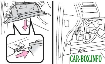
On RHD models, remove the glove box.
| Component Diagram & Layout | |
|---|---|
|
|
| F1 | 30A Body ECU / Power windows |
| F2 | 30 / 40A Turn signal flasher power supply / Rear window defogger (“MIR HTR” fuse) |
| F3 | 30A Seat heaters |
| R1 | Turn signal flasher relay |
| R2 | Blower motor / Heater relay |
| R3 | “IG1” relay - Ignition system |
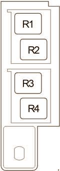
Relay Box No. 1
Diagram.
|
|
| R1 | Starter (ST) |
| R2 | Rear fog light (RR FOG) |
| R3 | Accessory relay (ACC) |
| R4 | Accessory cut relay (ACC CUT) |
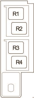
Relay Box No. 2
Diagram.
|
|
| R1 | Front fog lights (FR FOG) |
| R2 | Starter cut relay (ST CUT) |
| R3 | Panel relay (PANEL) |
| R4 | Spare |
