
The European-market Toyota Corolla Verso compact MPV was designed in Europe and manufactured in Turkey, built on the Corolla hatchback platform. Featuring dynamic styling, it showcases clever Japanese packaging to offer a unique interior layout that is compact yet remarkably spacious. Below is a detailed guide to the fuse box diagrams for the second-generation Toyota Corolla Verso (AR10 series, produced from 2004, 2005, 2006, 2007, 2008, 2009).

Below you will find the location, layout diagrams, and photos of the power distribution boxes. Fuses for the “Cigarette Lighter” and “Fuel Pump” are highlighted in bold.
Engine Compartment
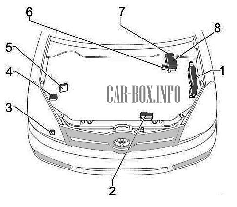
General layout of electronic components.
|
|
| No. | Component |
| 1 | Main fuse box |
| 2 | Relay box |
| 3 | Headlight washer relay |
| 4 | Vehicle Stability Control (VSC) module |
| 5 | Injector Driver Module (EDU) |
| 6 | Glow plug relay |
| 7 | Auxiliary fuse box (1ZZ-FE and 3ZZ-FE engines ) |
| 8 | Auxiliary fuse box (1CD-FTV engine ) |
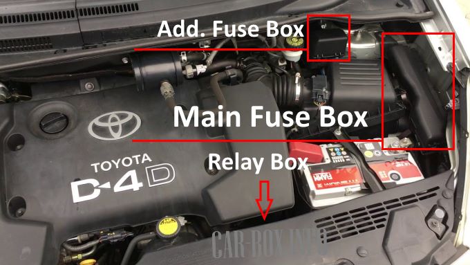
The main fuse box is located on the left side of the engine compartment, with the auxiliary fuse box mounted directly above it. The relay box is positioned underneath the battery beneath the protective trim panel.
Main Fuse Box
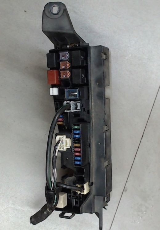
General view of the main fuse box.
| Diagram | ||
|---|---|---|
|
||
| No. | Description | A |
| 1 | Blank | - |
| 2 | ABS, VSC | 25 |
| 3 | Blank | - |
| 4 | Blank | - |
| 5 | Blank | - |
| 6 | ALT-S – Charging system | 7.5 |
| 7 | DCC – Fuses: “ECU-B2”, “DOME”, “RAD2” | 30 |
| 8 | AM2 – Ignition switch / Starting system, fuses: “ST”, “IGN” | 30 |
| 9 | HAZARD – Turn signals, hazard warning lights | 10 |
| 10 | F-HTR – 1CD-FTV: Fuel heater | 25 |
| 11 | HORN – Horn | 15 |
| 12 | EFI – Sequential multiport fuel injection system, fuses: “EFI1”, “EFI2” | 30 |
| 13 | PWR HTR – 1CD-FTV engine: Auxiliary heater | 25 |
| 14 | RR DEF – Rear window defogger | 30 |
| 15 | MAIN – Headlight washers, headlights, fuses: “H-LP HI LH”, “H-LP HI RH”, “H-LP LH”, “H-LP RH” | 40 |
| 16 | AM1 NO.1 – 1CD-FTV: Fuses: “ACC”, “CIG”, “RAD NO.1”, “ECU-B NO.1”, “FL P/W”, “FR P/W”, “RL P/W”, “RR P/W” | 50 |
| 17 | H-CLN – Headlight washers | 30 |
| 18 | HTR – Air conditioning / Heater system | 40 |
| 19 | CDS – Condenser cooling fan | 30 |
| 20 | RDI – 1CD-FTV, 1ZZ-FE, 3ZZ-FE engines: Radiator cooling fan | 40 |
| RDI – 1AZ-FE, 1AZ-FSE engines: Radiator cooling fan | 30 | |
| 21 | 1CD-FTV: ABS with VSC | 50 |
| 1CD-FTV: ABS without VSC | 40 | |
| 22 | IG2 – 1AZ-FSE, 1AZ-FE, 1ZZ-FE, 3ZZ-FE engines: Ignition system, sequential multiport fuel injection system | 15 |
| 23 | THROTTLE – 1AZ-FSE, 1AZ-FE, 1ZZ-FE, 3ZZ-FE: Electronic Throttle Control ECU | 15 |
| ETCS – 1AZ-FSE, 1AZ-FE, 1ZZ-FE, 3ZZ-FE: Electronic Throttle Control System | 10 | |
| 24 | A/F – 1AZ-FSE, 1AZ-FE: Air-fuel ratio sensor | 20 |
| 25 | 1AZ-FSE, 1AZ-FE, 1ZZ-FE, 3ZZ-FE: Blank | |
| 26 | ||
| 27 | EMPS – 1ZZ-FE, 3ZZ-FE: Electric Power Steering | 50 |
| Relay Module Functions | ||
| R1 | Radiator cooling fan 1CD-FTV (EFI MAIN) | |
| R2 | Radiator cooling fan 1CD-FTV (EDU) | |
| R3 | FAN3 – Radiator cooling fan 1CD-FTV | |
| R4 | FAN1 – Radiator cooling fan | |
| R5 | FAN2 – Radiator cooling fan (1AZ-FSE, 1AZ-FE, 1ZZ-FE, 3ZZ-FE) | |
| R6 | 1AZ-FSE, 1AZ-FE, 1ZZ-FE, 3ZZ-FE: Unused | |
| R7 | FAN3 – 1AZ-FSE, 1AZ-FE, 1ZZ-FE, 3ZZ-FE: Radiator cooling fan | |
| R8 | 1AZ-FSE, 1AZ-FE, 1ZZ-FE, 3ZZ-FE: Unused | |
| R9 | 1ZZ-FE, 3ZZ-FE engines: Electric Power Steering (EMPS) | |
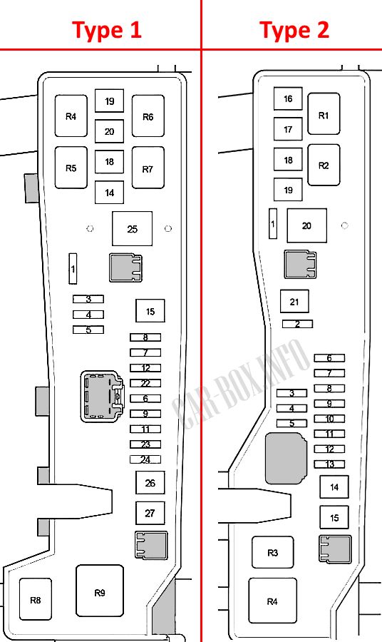
Auxiliary Fuse Box
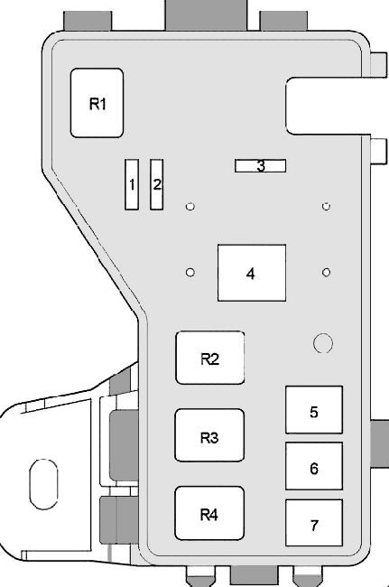
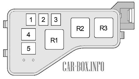
Layout diagram.
| Type 1 (1ZZ-FE, 3ZZ-FE engines) | ||
|
||
| R1 | INJ – Fuel injectors | - |
| R2 | EFI – Engine Control Module (ECM) | - |
| R3 | IG2 – Ignition system | - |
| R4 | A/F – Air-fuel ratio sensor | - |
| 1 | EFI1 – Multiport fuel injection system / sequential multiport fuel injection system | 10 |
| 2 | EFI2 – Emission control system | 7.5 |
| 3 | ABS, VSC | 25 |
| 4 | ALT – 1ZZ-FE, 3ZZ-FE: Fuses: “AM1 NO.1”, “H-LP CLN”, “ABS” (25A), “VSC” (25A), “ABS” (40A), “VSC” (50A), “CDS”, “RDI”, “HTR”, “RR DEF”, “RR FOG”, “FR FOG”, “AM1”, “DOOR”, “STOP”, “OBD2”, “S/ROOF”, “PWR SEAT”, “P/POINT”, “TAIL”, “PANEL”, “RR WIP”, “ECU-IG”, “WIP”, “GAUGE2”, “GAUGE1”, “HTR”, “S-HTR” | 100 |
| ALT – 1AZ-FSE, 1AZ-FE: Fuses: “AM1 NO.1”, “H-LP CLN”, “ABS” (25A), “VSC” (25A), “ABS” (40A), “VSC” (50A), “CDS”, “RDI”, “HTR”, “RR DEF”, “RR FOG”, “FR FOG”, “AM1”, “DOOR”, “STOP”, “OBD2”, “S/ROOF”, “PWR SEAT”, “P/POINT”, “TAIL”, “PANEL”, “RR WIP”, “ECU-IG”, “WIP”, “GAUGE2”, “GAUGE1”, “HTR”, “S-HTR” | 120 | |
| 5 | ABS with VSC | 50 |
| ABS without VSC | 40 | |
| 6 | AM1 NO.1 – Fuses: “PWR SEAT”, “FR DIC”, “FUEL OPN”, “ECU-B 1”, “P-RR P/W”, “P-FR P/W”, “D-RR P/W”, “D-FR P/W” | 50 |
| 7 | H-LP CLN – Headlight washers | 30 |
| Type 2 (1CD-FTV engine) | ||
|
||
| R1 | Unused | - |
| R2 | Auxiliary heater (HTR2) | - |
| R3 | Auxiliary heater (HTR1) | - |
| 1 | Blank | - |
| 2 | HTR2 – Auxiliary heater | 50 |
| 3 | HTR1 – Auxiliary heater | 50 |
| 4 | GLOW – Glow plugs | 80 |
| 5 | ALT – Relays: “IG1”, “TAIL”, “SEAT HTR”, fuses: “H-LP CLN”, “AM1 NO.1”, “RDI”, “CDS”, “VSC” (50A), “VSC” (25A), “ABS” (40A), “ABS” (25A), “H/CLN”, “RR DEF”, “GLOW”, “HTR NO.1”, “HTR NO.2”, “RFG HTR”, “AM1 NO.2”, “RR FOG”, “S/ROOF”, “STOP”, “P/POINT”, “FR FOG”, “OBD2”, “DOOR” | 140 |
Relay Box
Layout diagram.

|
||
| No. | Description | A |
| R1 | HORN – Horn relay | - |
| R2 | F-HTR – Fuel heater relay | - |
| R3 | H-LP – Headlight relay | - |
| R4 | DIM – Headlight dimmer relay | - |
| R5 | FAN2 – Radiator cooling fan relay | - |
| 1 | H-LP HI LH – Left headlight (high beam) | 10 |
| 2 | H-LP HI RH – Right headlight (high beam), instrument cluster | 10 |
| 3 | H-LP LH – Left headlight (low beam) | 15 |
| 4 | H-LP RH – Right headlight (low beam) | 15 |
Passenger Compartment
General layout of electronic components.

Left-hand drive (LHD) models. |
|
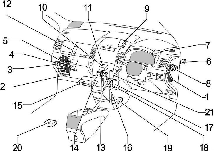
Right-hand drive (RHD) models. |
|
| No. | Component |
| 1 | Auxiliary fuse box |
| 2 | Body Control Module (BCM) |
| 3 | Rear window defogger relay |
| 4 | Toyota Corolla Verso Fuel Pump Relay (Circuit Opening Relay) |
| 5 | Main fuse box |
| 6 | Turn signal flasher / hazard relay |
| 7 | Keyless entry / central locking receiver |
| 8 | Power distribution junction block |
| 9 | Immobilizer transponder ECU |
| 10 | Automatic climate control module |
| 11 | A/C amplifier |
| 12 | Engine Control Module (ECM) |
| 13 | Relay Box No. 2 |
| 14 | Relay Box No. 3 |
| 15 | Transmission Control Module (TCM) |
| 16 | Relay Box No. 1 |
| 17 | Windshield wiper relay |
| 18 | Parking assist ECU (Clearance sonar) |
| 19 | Supplemental Restraint System (SRS) airbag ECU |
| 20 | Rearview camera ECU |
| 21 | Ignition control module / Igniter |
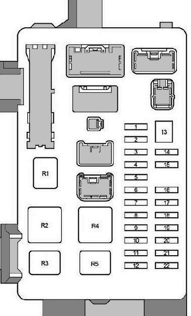
Main Fuse Box

On left-hand drive (LHD) vehicles, the main fuse box is located on the driver's side at the bottom of the lower instrument panel behind a cover, with the auxiliary fuse box positioned adjacent to it. On right-hand drive (RHD) models, the main fuse box is located on the passenger side behind the glove box, while the auxiliary fuse box is on the driver's side behind a protective panel.
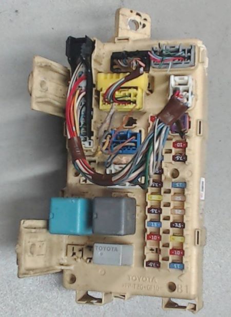
Example view of the main fuse box.
| Diagram | ||
|---|---|---|
|
||
| No. | Description | A |
| 1 | IGN – SRS airbags, instrument cluster, starting system, sequential multiport fuel injection system | 10 |
| 2 | Sunroof / Moonroof | 20 |
| 3 | RR FOG – Rear fog lights | 7.5 |
| 4 | FR FOG – Front fog lights, fog light indicator | 15 |
| 5 | AM1 – Starting system, fuses: “CIG”, “RAD1” | 25 |
| 6 | Instrument panel illumination, instrument cluster backlighting, automatic transmission control unit, glove box light, console box light, headlight washers, front fog lights, parking assist system, multi-information display (PANEL) | 7.5 |
| 7 | RR WIP – Rear wiper and washer | 20 |
| 8 | Reverse lights, headlight leveling system, turn signal lights, hazard warning lights (GAUGE2) | 7.5 |
| 9 | CIG – Toyota Corolla Verso Cigarette Lighter Fuse | 15 |
| 10 | HTR – Seat heaters, air conditioning system | 10 |
| 11 | Blank | - |
| 12 | RAD1 – Audio system, multi-information display, power mirrors, instrument cluster, accessory socket | 7.5 |
| 13 | PWR SEAT – Power seats | 30 |
| 14 | TAIL – Tail lights, license plate lights, luggage compartment light, automatic headlight system, front fog lights, rear fog lights, instrument cluster | 10 |
| 15 | OBD2 – On-Board Diagnostics (OBD-II) connector | 7.5 |
| 16 | P/POINT – 12V auxiliary power outlet | 15 |
| 17 | DOOR – Power door locks | 25 |
| 18 | WIP – Front windshield wiper and washer, headlight washers | 25 |
| 19 | ECU-IG – Radiator cooling fan, charging system, power steering, ABS, VSC | 7.5 |
| 20 | Seat heaters (S-HTR) | 20 |
| 21 | Headlight switch, multi-information display, integrated relay, instrument cluster, shift lock system, automatic transmission ECU, electrochromic rear view mirror, windshield wiper, parking brake indicator (GAUGE1) | 10 |
| 22 | Brake lights, shift lock system, high-mounted stop light, sequential multiport fuel injection system (STOP) | 15 |
| R1 | Spare | - |
| R2 | HTR – Blower motor / heater relay | - |
| R3 | SEAT HTR – Seat heater relay | - |
| R4 | IG1 – Ignition relay | - |
| R5 | TAIL – Tail light relay | - |
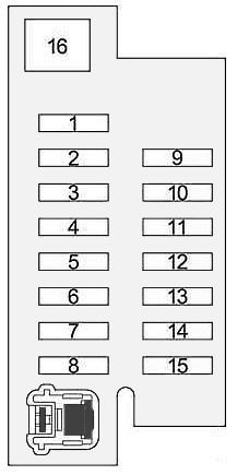
Auxiliary Fuse Box
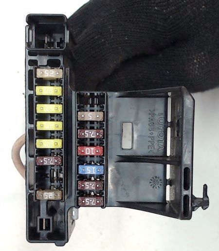
General view.
| Diagram | ||
|---|---|---|
|
||
| No. | Description | A |
| 1 | ACC – Push-button start, immobilizer, steering column lock (LHD) | 25 |
| 2 | Power Window – Rear passenger-side power window (P-RR P/W) | 20 |
| 3 | Power Window – Front passenger-side power window (P-FR P/W) | 20 |
| 4 | Power Window – Rear driver-side power window (D-RR P/W) | 20 |
| 5 | Power Window – Front driver-side power window (D-FR P/W) | 20 |
| 6 | ECU-B 1 – Automatic transmission control | 7.5 |
| 7 | FUEL OPN – Fuel filler door release | 10 |
| 8 | FR DIC – Windshield wiper de-icer, fuse: “MIR HTR” | 20 |
| 9 | A/C – Manual air conditioning, auxiliary heater | 10 |
| 10 | DEF I/UP – Air conditioning idle-up system | 7.5 |
| 11 | ST – Multi-information display, sequential multiport fuel injection system, starting system | 7.5 |
| 12 | MIR HTR – Heated exterior mirrors | 10 |
| 13 | RAD NO.2 – Audio system, multimedia display | 15 |
| 14 | DOME – Interior dome light, reading lights, door courtesy lights, luggage compartment light, vanity mirror lights, footwell illumination | 7.5 |
| 15 | ECU-B 2 – Air conditioning ECU, keyless entry receiver | 7.5 |
| 16 | PWR SEAT – Power seats | 30 |
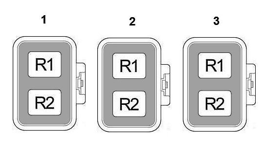
Relay Boxes
Description and relay allocation.
|
|
| Relay Box No. 1 | |
| R1 | ACC – Accessory relay |
| R2 | ST – Starter relay |
| Relay Box No. 2 | |
| R1 | 12V power outlet relay |
| R2 | IG2 – Ignition relay |
| Relay Box No. 3 | |
| R1 | Front fog light relay |
| R2 | Rear fog light relay |
Body Electrical Components
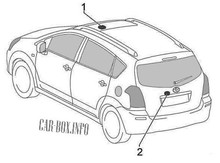
Components:
- Sunroof control module,
- Rear wiper relay

Very good apply