
The Toyota Corolla has been in continuous production since 1966. Unveiled at the Guangzhou Motor Show in November 2018, the 12th-generation model is built on Toyota’s modular TNGA (E210) platform and shares core design elements with the Prius. This guide provides detailed fuse box diagrams and circuit assignments for the 12th-generation Toyota Corolla (chassis code E210 / GA-C platform) covering model years 2019, 2020, 2021, 2022, 2023, 2024, and 2025.
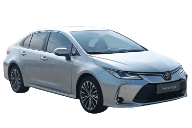
Below are the locations, diagrams, and photos of the power distribution boxes. The fuse assigned to the “cigarette lighter” (auxiliary power outlet) is highlighted in bold.
Engine Compartment

The main fuse box is located on the left side of the engine compartment beneath a protective cover.

Fuse box cover removal and access.
Fuse Box Diagram

Designation | Protected Circuit
ABS MTR NO.1 | Anti-lock brake system (ABS) motor No. 1
ABS-MAIN | Anti-lock brake system (ABS) main control unit
AMP | Audio system amplifier
CM/MAYDAY | Data Communication Module (DCM) / Telematics system
DEF | Rear window defogger
DEICER | Windshield wiper de-icer
DOOR DBL/L | Double door locking system
DRL DBL/L | Daytime running lights (DRL)
ECU-IG2 NO.1 | Electronic Control Unit (IG2 No. 1)
EFI NO.1 | Electronic Fuel Injection system No. 1
EFI NO.2 | Electronic Fuel Injection system No. 2
EFI NO.3 | Electronic Fuel Injection system No. 3
EFI NO.4 | Electronic Fuel Injection system No. 4
EFI NO.5 | Electronic Fuel Injection system No. 5
EFI-MAIN NO.2 | Electronic Fuel Injection main system No. 2
EFI-MAIN NO.3 | Electronic Fuel Injection main system No. 3
EPS | Electric Power Steering (EPS)
FAN NO.1 | Radiator cooling fan No. 1
FAN NO.2 | Radiator cooling fan No. 2
H-LP HI | High-beam headlights
H-LP LH | Left headlight
H-LP RH | Right headlight
HORN | Horn
HTR | Air conditioning / Heating system
IG2-MAIN | Ignition No. 2 main circuit protection
J/B-B | Junction box B
MIR HTR | Heated side mirrors
P/OUTLET NO.2 | Cigarette lighter / Auxiliary power outlet No. 2
PTC HTR NO.1 | PTC auxiliary heater No. 1
PTC HTR NO.2 | PTC auxiliary heater No. 2
PTC HTR NO.3 | PTC auxiliary heater No. 3
S/HTR RR | Heated rear seats
S/HTR-MAIN | Heated seats main circuit
S-HORN | Anti-theft alarm horn
SPARE | Spare fuse
ST | Starter system
STRG HTR | Heated steering wheel
STRG LOCK-IG2 | Steering column lock
WIPER | Windshield wipers
Passenger Compartment

The interior fuse box is located under the left side of the instrument panel.

Fuse box location and access.
| Fuse Box Diagram | ||
|---|---|---|

|
||
| Fuse | Rating | Protected Circuit / Function |
| FOG RR | 7.5 A | Rear fog lights |
| OBD | 7.5 A | On-Board Diagnostics (OBD-II) system |
| DOME | 7.5 A | Interior illumination and dome lights |
| ECU-DCC | 10 A / 5 A | Electronic Control Unit (DCC) |
| RADIO | 15 A | Audio system / Radio |
| DOOR R/R | 20 A | Rear right door control / power window |
| STRG LOCK | 10 A | Electric steering column lock |
| ECU-ACC | 5 A | Accessory ECU |
| ECU-IG1 | 7.5 A | Ignition ECU No. 1 |
| EPS-IG1 | 5 A | Electric Power Steering (EPS) system |
| A/BAG-IG2 | 10 A | Supplemental Restraint System (SRS) airbag |
| METER-IG2 | 5 A | Instrument cluster / Combination meter |
| ECU-IG2 | 5 A | Ignition ECU No. 2 |
| ECU-B | 10 A / 5 A | Body ECU / Battery ECU |
| D/L | 20 A | Power door locks |
| STOP | 7.5 A | Stop lights (Brake lights) |
| AM2 | 7.5 A | Ignition switch / Starter circuit |
| HAZ | 10 A | Hazard warning flashers |
| PANEL | 5 A | Instrument panel illumination |
| TAIL | 10 A | Tail lights, parking lights, and license plate lights |
| DOOR | 20 A | Main door lock / Power window system |
| DOOR R/L | 20 A | Rear left door control / power window |
| P/OUTLET 1 | 15 A | Auxiliary power outlet No. 1 (Cigarette lighter fuse) |
| SFT LOCK - ACC | 5 A | Shift lock control system |
| WASHER | 15 A | Windshield washer pump |
| WIPER | 15 A | Windshield wipers |
| BKUP LP | 7.5 A | Reverse (backup) lights, audio system, display monitor, navigation |
