Toyota Corolla E120 E130 represents the 9th generation of the Corolla model range which was produced in 2000, 2001, 2002, 2003, 2004, 2005, 2006 and 2007 with left and right hand drive. Delivered all over the world (America, Europe, Asia) with various body options. Also known as Toyota Fielder. In this publication you will find a description of fuses and relays Corolla E120/E130 (Fielder) with block diagrams and their layout. The fuse responsible for the “cigarette lighter” is highlighted in bold.
The design of the blocks and the purpose of the elements in them may differ from the one presented and depends on the year of manufacture, the level of equipment and the region of delivery of your car (Right or Left hand drive). Check the assignment with your diagrams on the block cover.
General arrangement of blocks
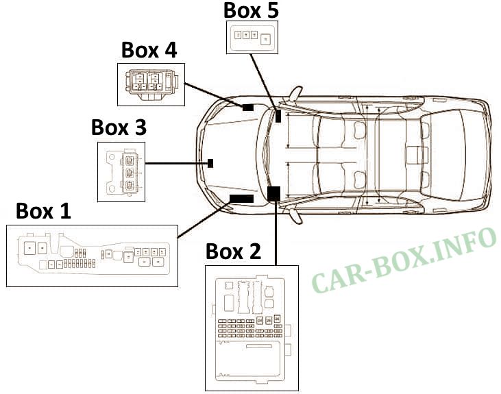
In total, this model provides 5 main blocks with fuses and relays, as well as individual elements can be installed outside of them.
In the engine compartment
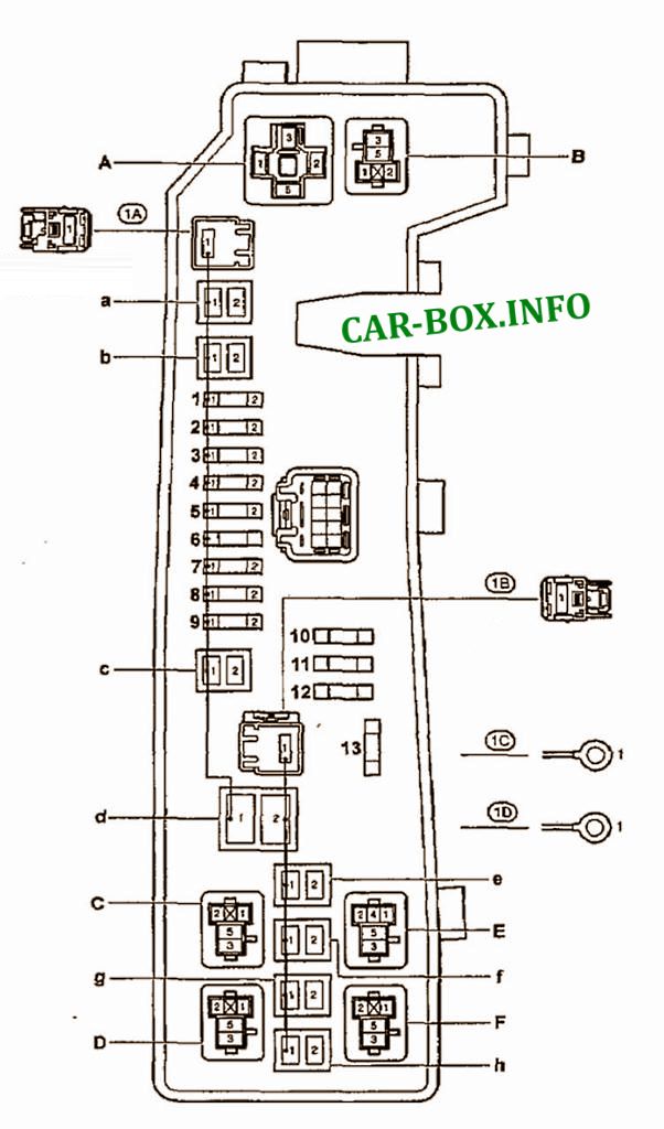
Main fuse box
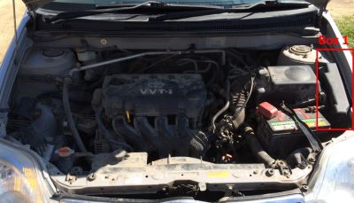
In the general diagram, it is designated as Box 1. Located on the left side, next to the battery.
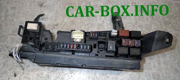
General view.
| Diagram | |
|---|---|
|
|
| № | Amps / Description |
| A | Power steering relay |
| B | Relay e / m air conditioning compressor clutch |
| C | Horn relay |
| D | Injection system relay |
| E | Radiator fan relay # 2 |
| F | Radiator fan relay # 1 |
| a | EMPS (50A) - electric power steering |
| b | HEAD MAIN (40A) - headlamps |
| c | A / PUMP (50A) - engine management (2ZZ-GE) |
| d | ALT (100A) - charging system, rear window heater |
| e | H-LP CLN (30A) - headlight washer |
| f | RDI FAN (30A) - radiator and condenser fans |
| g | ABS No. 1 (30A) or VSC No. 1 (40A) - ABS |
| h | ABS No. 2 (40A) or VSC No. 2 (40A) - ABS |
| 1 | HEAD RH (15A) - right headlamps |
| 2 | HEAD LH (15A) - left headlamps |
| 3 | HORN (10A) - sound signal |
| 4 | HAZARD (10A) - direction indicators and hazard warning lamps |
| 5 | ALT-S (5A) - charging system |
| 6 | spare |
| 7 | EFI (15A) - engine management, automatic transmission mode indicators, headlights, interior lamps, automatic air conditioning, radio, warning system about not turned off lights, remote central locking control, ABS (VSC) |
| 8 | DOME (15A) - clock, instrument cluster, headlights, interior lighting, air conditioning with automatic, control, radio, warning system, lights not turned off, remote control |
| 9 | AM2 (30A) - circuit AM2 of the ignition lock |
| 10 | backup circuit |
| 11 | backup circuit |
| 12 | backup circuit |
| 12 | backup circuit |
Block #3
Installed next to radiators and cooling fans.
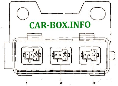
Description:
№1/2/3 - Radiator fan relay
Block #4
Can be installed on the right side of the engine compartment.
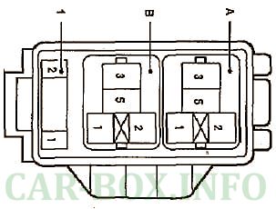
- A - ABS electric pump relay;
- B - ABS valve relay;
- 1 - 7.5A ABS (VSC)
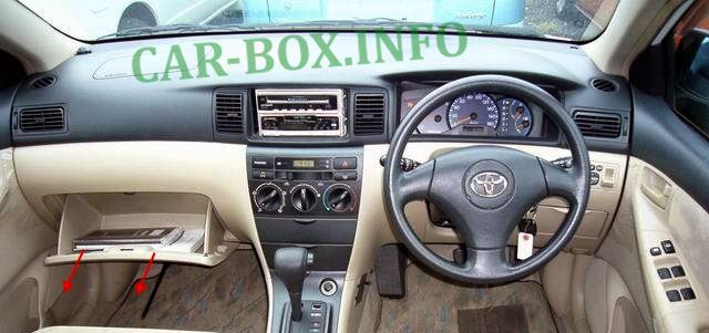
In the passenger compartment
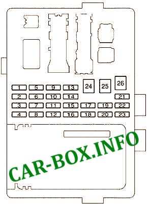
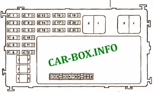
Main fuse box
Left hand drive
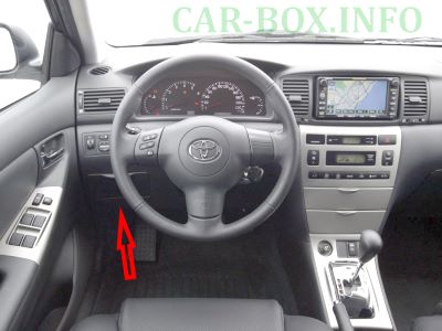
The glove box must be removed to access.
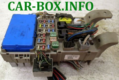
General view.
| Assigment of fuses in the passenger compartment (LHD) | |
|---|---|
|
|
| № | Amps / Description |
| 1 | not used |
| 2 | not used |
| 3 | not used |
| 4 | 25А FUEL HTR - Fuel heater |
| 5 | 15А CIG - Cigarette lighter , audio system, clock, controls for electric drive rear-view mirrors |
| 6 | 15A IG2 - Sensors and meters, SRS air bag system, multi-channel fuel injection system / sequential multi-channel fuel injection system, starter system, charging system |
| 7 | 10А М-НТR / DEF I-UP - Anti-fogging of external mirrors, multi-channel fuel injection system / sequential multi-channel fuel injection system |
| 8 | 7,5А ST - Starter, multi-channel fuel injection system / sequential multi-channel fuel injection system, sensors and counters |
| 9 | 10A ECU-B - Air conditioning system, anti-lock brake system, vehicle stability control system, rear fog lamp |
| 10 | 25А AM1 - Fuse "CIG" |
| 11 | 15A TAIL - Tail lamps, Rear lamp, license plate lamps, parking lamps, headlight beam control system, dashboard lamps, clock, headlight cleaner, front fog lamps, seat heaters, multi-channel fuel injection system / sequential multi-channel injection system fuel |
| 12 | 20A P / V - Driver power window |
| 13 | 15A STOP - Brake lights, high set brake light, gear lock control system, multi-channel fuel injection system / sequential multi-channel fuel injection system, anti-lock brake system, vehicle stability control system |
| 14 | 15A FOG - Front fog lamps |
| 15 | 25A DOOR - Electric drive door locking system |
| 16 | not used |
| 17 | 10А А / С - Air conditioning system |
| 18 | 7.5А ОВD - On-board diagnostic system |
| 19 | 10А GAUGE - Sensors and meters, air conditioning system, electric drive windows, reverse signals, daytime running light system, anti-fog rear window, automatic transmission upshift system, electric drive door locking system, charging system, emergency flashing signals, automatic anti-glare interior rearview mirror, airbag system SRS, reminiscent of the front passenger seat belt indicator lamps |
| 20 | 15A S-НТR - Seat heaters |
| 21 | 15А WASH - Windscreen wipers and windshield washer |
| 22 | 10A ECU-IG - SRS Airbag System, Electric Cooling Fan, Antilock Brake System, Gear Lock Control System, Power Steering System, Headlight Washer |
| 23 | 25A WIPER - Windshield wipers and glass washer of a windshield, windshield wipers and glass washer of a rear window |
| 24 | 40А DEFOG - Anti-fogging of the rear window, "M-HTR / DEF I-UP" fuse |
| 25 | 30A POWER - Power window, electric sunroof |
| 26 | 40A NEATER - Air conditioning system, fuse "A / C" |
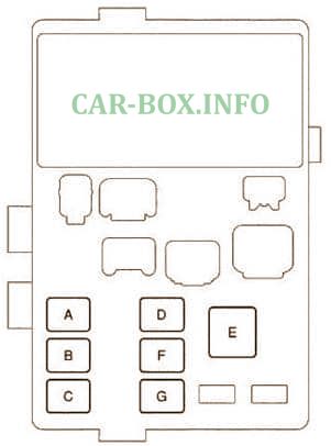
| Relay circuit on the back of the unit | |
|
|
| A | Ignition relay |
| B | Heated rear window relay |
| C | Fuel pump relay |
| D | Power windows |
| E | Starter relay |
| F | Power windows, electric sunroof |
| G | Heated rear window, air conditioner, heater |
Right hand drive
To access, unscrew the screw, disconnect the clips and remove the glove compartment.
| Assigment of fuses in the passenger compartment (RHD) | |
|---|---|
|
|
| № | Description |
| a | POWER 30A - power windows, electric sunroof |
| b | DEFOG 30A - Heated rear window |
| c | HEATER 40A - air conditioner, heater. |
| 1 | WASH 15A - wipers and washers |
| 2 | ECU-KZ 10A - ABS, electric power steering, radiator and condenser fans |
| 3 | GAUGE 10A - instrument cluster, direction indicators and hazard warning systems, warning systems for unfastened seat belts and forgotten key, central locking |
| 4 | backup circuit |
| 5 | backup circuit |
| 6 | backup circuit |
| 7 | WIPER 25A - wipers and washers |
| 8 | TAIL 15A - tail lamps, rear fog lamp, warning system about not turned off lighting, headlamps |
| 9 | STOP 15A - brake lights, engine management, automatic transmission and ABS indicators |
| 10 | DOOR 25A - central locking, interior lighting, warning system, wireless central locking control |
| 11 | P / W 20А - power windows |
| 12 | Spare |
| 13 | AM1 25A - circuit AM1 of the ignition lock |
| 14 | ECU-B 7.5A - fog lamps, engine control module and automatic transmission module |
| 15 | FOG 15A - front fog lamps |
| 16 | ST 7,5A - instrument cluster, engine control module, starter |
| 17 | A / C 25A - air conditioner |
| 18 | IG2 15A - ABS, charging system, automatic transmission, electric power steering, engine management, ignition, SRS |
| 19 | DEF I-UP 10A - Engine Management, Heated Rear Window |
| 20 | Reserve |
| 21 | CIG 15A - cigarette lighter, radio, navigation system, clock, mirror adjustment |
| Relay circuit on the back of the unit | |

|
|
| A | Ignition relay |
| B | Heated rear window relay |
| C | Fuel pump relay |
| D | Relay for electric drive glass lifters |
| E | Starter relay |
Additional relay box
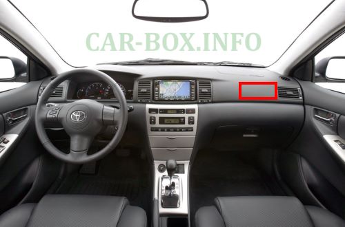
In the general diagram, it is designated as Block #5, it is located under the panel on the right side.
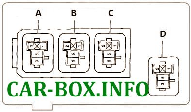
Appointment
- A - Relay control system h / idle;
- B - Fog lamp relay;
- C - Relay for accessories;
- D - Heater relay

Thanks for helping us