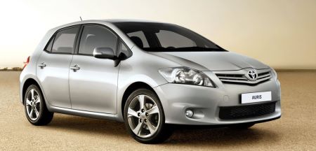
The 1st generation Toyota Auris (E150) was produced in 2006, 2007, 2008, 2009, 2010, 2011, 2012 and 2013 as a hatchback and delivered worldwide. During this time, the model has been restyled. In this material you will find information describing the location of electronic control units, consider in detail the Toyota Auris fuse and relay blocks with diagrams and photo examples of execution. Highlight the cigarette lighter fuse.
The number of elements in the blocks and their purpose may differ from the one presented. Check the description against the diagrams on the protective cover of the distribution block.
In the engine compartment

The layout of the engine compartment equipment:
- Engine control unit;
- The main block of fuses and relays;
- Glow plug relay;
- Control unit for the cooling fan;
- Left hand drive: Headlight wiper relay;
- Injector control unit (EDU);
- Relay box;
- Gasoline: Brake system control unit;
- Diesel: Brake system control unit
Main fuse box
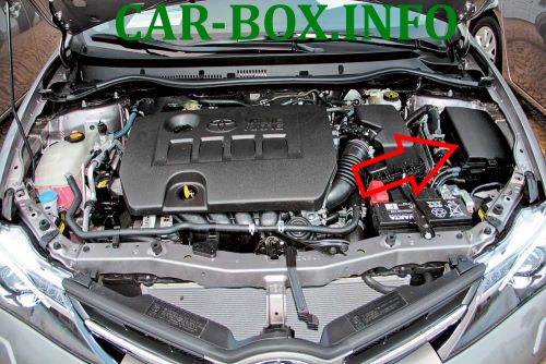
The fuse block is closed with a protective plastic cover.

General view.
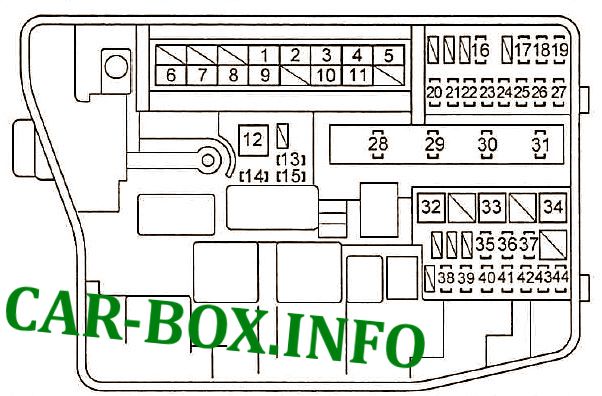
Type 1
Diagram.
|
||
| No. | Decoding | A |
| 1 | headlight washer | 30 |
| 2 | Cooling fan | 40 |
| 3 | ABS system, VSC No. 3 | 30 |
| 4 | ABS system, VSC No. 1 | 50 |
| 5 | Air conditioning | 50 |
| 6 | ALT: Charging system, fuse circuit "RDI FAN", "H - LP CLN", "ABS No. 1", "ABS No. 3", "ABS No. 2", "HTR", "HTR SUB No. 1", "HTR SUB # 2 "," HTR SUB # 3 "," STV HTR "," ACC "," CIG "," METER "," IGN "," ECU - IG # 2 "," HTR - IG "," WIPER " , "RR WIPER", "WASHER", "ECU - IG No. 1", "SEAT HTR", "AM1", "DOOR", "RL DOOR", "STOP", "FR DOOR", "POWER", " RR DOOR "," OBD "," ACC - B "," RR FOG "," FR FOG "," DEF "," MIR HTR "" TAIL "," PANEL " | 120 |
| 7 | Electric power steering | 60 |
| 8 | GLOW | - |
| 9 | P-SYSTEM | - |
| 10 | Fuse circuit "EFI MAIN", "HORN", "IG2", "EDU" | 50 |
| 11 | Fuse circuit "H - LP LH LO", "H - LP RH LO", "H - LP LH HI", "H - LP RH HI" | 50 |
| 12 | Manual transmission (Multimode) | 50 |
| 13 | Spare | 10 |
| 14 | 30 | |
| 15 | 20 | |
| 16 | Manual transmission (Multimode), air conditioning, "Smart Entry & Start" system | 10 |
| 17 | ECU - B: Engine Control Unit, Instrument Cluster, VSC, Power Windows | 10 |
| 18 | Radio cassette | 15 |
| 19 | Interior lighting, luggage compartment lighting, Smart Entry & Start system | 10 |
| 20 | Engine control unit AM2 No. 2 | 7.5 |
| 21 | ALT - S charging system | 7.5 |
| 22 | Alarm | 10 |
| 23 | Throttle valve control unit | 10 |
| 24 | AM2: Start system, "Smart Entry & Start" system, injection system | 30 |
| 25 | A / F: Exhaust system | 20 |
| 26 | Steering lock system | 20 |
| 27 | IGT / INJ | - |
| 28 | EDU: Start system, "Smart Entry & Start" system | 20 |
| 29 | EFI MAIN: Injection system, "EFI No. 1", "EFI No. 2" fuse circuit | 20 |
| 30 | Sound signal (horn) | 10 |
| 31 | IG2: Injection system, starting system, "Smart Entry & Start" system, IG, Meter, IG No. 2 circuits | 15 |
| 32 | Conditioner HTR SUB No. 1, 2, 3 | 30 |
| 33 | 30 | |
| 34 | 30 | |
| 35 | FR DEICER | - |
| 36 | ABS, VSC | 30 |
| 37 | STV HTR | - |
| 38 | IG # 2: Starting system, "Smart Entry & Start" system | 7.5 |
| 39 | EFI # 2: Injection system | 10 |
| 40 | 10 | |
| 41 | Right headlamp (high beam) | 10 |
| 42 | Left headlamp (high beam) | 10 |
| 43 | Right headlamp (low beam) | 15 |
| 44 | Left headlamp (low beam) | 15 |
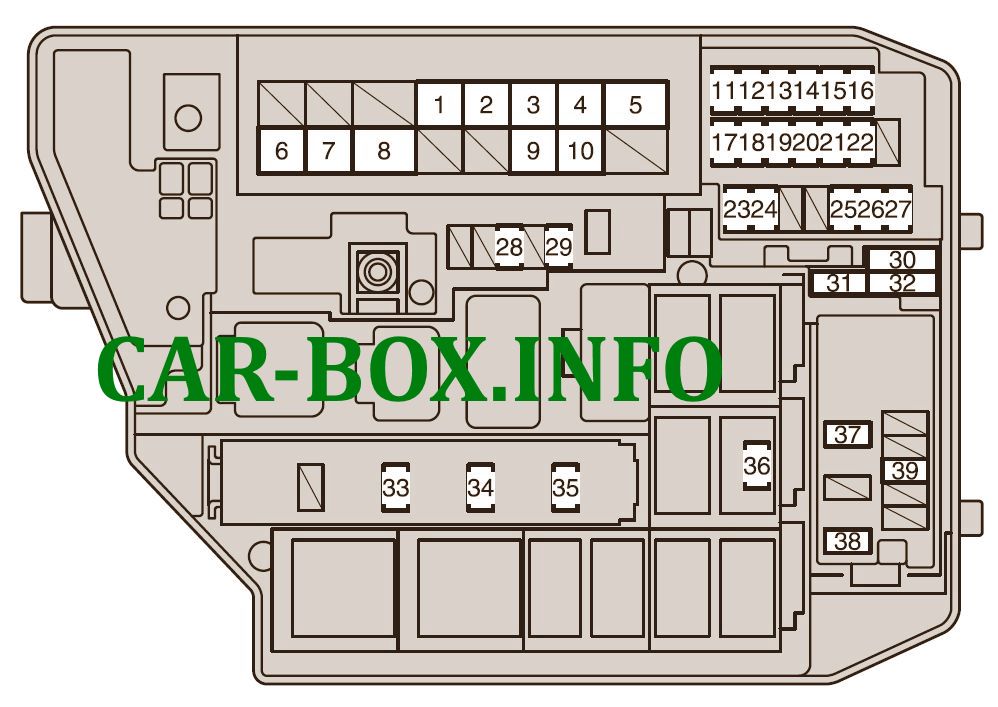
Type 2
Diagram.
|
||
| No. | Description | A |
| 1 | 30A CDS FAN - Electric cooling fan (s) | 30 |
| 2 | RDI FAN - Electric cooling fan (s) | 40 |
| 3 | ABS NO. 3 - Anti lock braking system, vehicle stability control system | 30 |
| 4 | ABS NO. 1 - Anti lock brake system, vehicle stability control system | 50 |
| 5 | HTR - Air conditioning system | 50 |
| 6 | ALT - Charging system, RDI FAN, CDS FAN, ABS NO. 1, ABS NO. 3, HTR, NUMBER HTR. 1, HTR SUB NO. 3, ACC, CIG, METER, IGN, ECU-IG NO. 2, HTR-IG, wiper, washer, ECU-IG NO. 1, AM1, DOOR, STOP, FRONT DOOR, POWER, BACK DOOR, BACK DOOR, OBD, ACC-B, FR FOG, DEF, MIR HTR, REAR, PANEL | 120 |
| 7 | EPS - Electric power steering | 60 |
| 8 | GLOW - Glow plugs | 80 |
| 9 | P / I - EFI MAIN, HORN, IG2 | 50 |
| 10 | H-LP MAIN - headlamps | 50 |
| 11 | EFI NO. 2 - Emission control system | 10 |
| 12 | EFI NO. 1 - Multiport fuel injection system / sequential multiport fuel injection system | 10 |
| 13 | H-LP RH HI - Right headlamp (high beam) | 10 |
| 14 | H-LP LH HI - Left headlamp (high beam) | 10 |
| 15 | H-LP RH LO - Right headlamp (low beam) | 10 |
| 16 | H-LP LH LO - Left headlamp (low beam) | 10 |
| 17 | ETCS - Electronic Throttle Control System | 10 |
| 18 | TURN-HAZ - Direction indicators, emergency flashers | 10 |
| 19 | ALT-S - Charging system | 7.5 |
| 20 | AM2 NO. 2 - Multiport fuel injection system / sequential multiport fuel injection system, starting system | 7.5 |
| 21 | AM2 - Starting system | 30 |
| 22 | STRG LOCK - Steering lock system | 20 |
| 23 | IG2 NO.2 - Starting system | 7.5 |
| 24 | ECU-B2 - Air conditioning system | 10 |
| 25 | ECU-B - Main body ECU, sensor and meters | 10 |
| 26 | RAD NO. 1 - Audio system | 15 |
| 27 | DOME - Trunk lamps, Smart Key System | 10 |
| 28 | AMP - Audio System | 30 |
| 29 | MAYDAY | 10 |
| 30 | SPARE | 10 |
| 31 | SPARE | 30 |
| 32 | SPARE | 20 |
| 33 | EFI MAIN - Multiport fuel injection system / sequential multiport fuel injection system, EFI NO. 1, EFI NO. 2 | 20 |
| 34 | HORN -Sound Signal | 10 |
| 35 | IG2 - Multiport fuel injection system / sequential multiport fuel injection system, starting system, IGN, METER | 15 |
| 36 | ST - Starter | 7.5 |
| 37 | HTR SUB NO. 1 - PTC heater | 30 |
| 38 | HTR SUB NO. 3 - PTC heater | 30 |
| 39 | PWR OUTLET / INVERTER or PWR OUTLET - Socket, cigarette lighter | 15 |
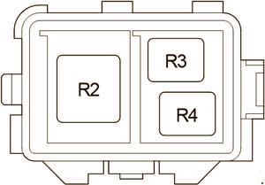
Relay box
Additional relay board.
| Diagram | |
|---|---|
|
|
| No. | Decoding |
| R2 | Auxiliary heater (HTR SUB) |
| R3 | |
| R4 | |
In the passenger compartment
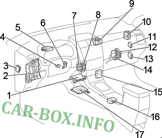
General diagram of the electrics in the cabin
1. Air conditioning control unit;
2. Fuse box / Body ECU;
3. Left hand drive: Headlight range control unit;
4. Steering wheel lock control unit;
5. Power steering control unit;
6. Key transponder amplifier;
7. Relay box No. 1;
8. Relay box No. 2;
9. Distribution block;
10. Distribution block;
11. Wiper relay;
12. Left hand drive: Transmission control unit (Multi-mode);
13. Engine and gearbox control unit;
14. Control unit for start-stop system;
15. Multimedia interface control unit;
16. Left hand drive: Transmission selector lock control unit;
17. Airbag control unit;
18.Right Drive: Turn Signal Relay
Fuse block "A"
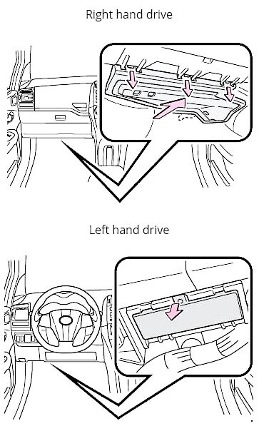
There are two fuse boxes located here. Block A is located on the driver's side at the bottom of the dashboard under a plastic cover.
Squeeze the cover latch to access the unit.
| Assigment of fuses in the passenger compartment | ||
|---|---|---|
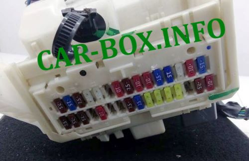
General view. |
||
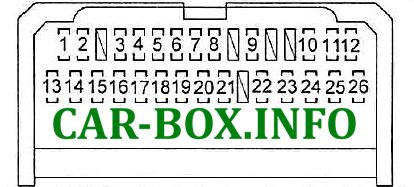
Diagram. |
||
| No. | Description | A |
| 1 | Headlamps, rear combination lamps, license plate lamps, rear fog lamps, front fog lamps, injection system, instrument panel lamps | 10 |
| 2 | Interior light switch, instrument panel light, glove box light, steering wheel switches | 7.5 |
| 3 | Power windows for front doors | 20 |
| 4 | Power window, rear left door | 20 |
| 5 | Power window, rear right door | 20 |
| 6 | Sunroof | 20 |
| 7 | Auris cigarette lighter fuse | 15 |
| 8 | Power side mirrors, engine control unit, "Smart Entry & Start" system, gear locking system | 7.5 |
| 9 | Heated side mirrors, injection system | 10 |
| 10 | Rear fog lights | 7.5 |
| 11 | Steering lock system, SRS, manual transmission {Multimode), injection system, "Smart Entry & Start" system | 7.5 |
| 12 | Instrument cluster | 7.5 |
| 13 | Seat heater | 15 |
| 14 | Air conditioning, rear window defogger | 10 |
| 15 | Wiper | 25 |
| 16 | Empty | - |
| 17 | Windshield washer | 15 |
| 18 | ECU-IG No. 1: Headlight range control unit, engine control module, electric cooling fan, gear locking system, rain sensor, ABS, VSC, radio, injection system, "Smart Entry & Start" system | 10 |
| 19 | ECU-IG # 2: Reversing lights, charging system, heated rear window, air conditioning, hazard warning lights, front passenger seat belt not fastened indicator | 10 |
| 20 | OBD diagnostic system | 7.5 |
| 21 | Brake lights, auxiliary brake light, ABS system, VSC, ECM, injection system, manual transmission (Multimode) | 10 |
| 22 | Door lock system | 25 |
| 23 | Fuse circuit "CIG", "ACC" | 25 |
| 24 | Empty | - |
| 25 | Front fog lamps | 15 |
| 26 | AM-1 : Starting system, "Smart Entry & Start" system, gear blocking system, "CIG", "ACC" fuse circuit | 7.5 |
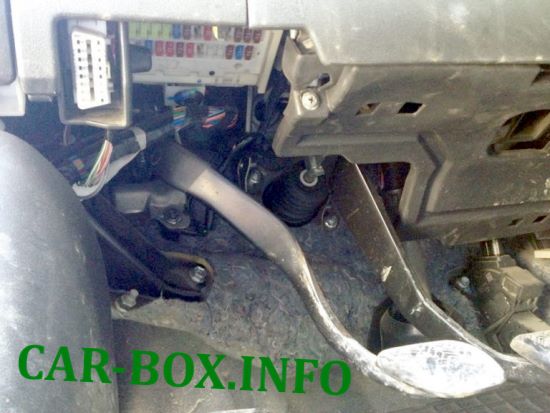
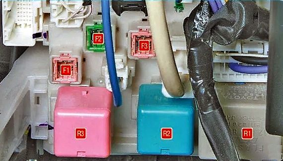
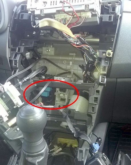
Fuse block "B"
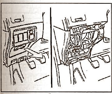
The location of the unit (B) is shown in the picture above.
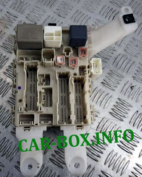
Photo is an example of execution.
| Diagram | ||
|---|---|---|

|
||
| No. | Appointment | A |
| 1 | Power windows | 30 |
| 2 | Heated rear window, "MIR HTR" fuse circuit | 40 |
| 3 | PWR SEAT | - |
|
||
| R1 | Relay - turn signal interrupter | |
| R2 | Heater relay | |
| R3 | Relay "IG1" - ignition system | |
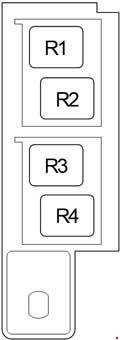
Additional relay box
Location.
| Diagram | |
|---|---|
|
|
| No. | Description (Relay box #2) |
| R1 | Front fog lamps (FR FOG) |
| R2 | Starter (ST CUT) |
| R3 | Panel (PANEL) |
| R4 | Spare |
| No. | Purpose (Relay box #1) |
| R1 | Starter (ST) |
| R2 | Rear fog lamps (RR FOG) |
| R3 | Auxiliary relay (ACC) |
| R4 | Auxiliary relay (ACC CUT) |
