Table of Contents
Most of the electrical circuits in the Japanese sedan's are protected by fuses. Headlights, fan motors, fuel pump and other powerful current consumers are connected via relays. Protective elements are installed in distribution boxes located in the passenger compartment and under the hood.

In this article, we will take a detailed look at the fuse box diagrams for the Toyota Camry XV40 2006, 2007, 2008, 2009, 2010, 2011 release.
In the passenger compartment

The fuse box is located on the left side of the dashboard underneath a plastic cover.
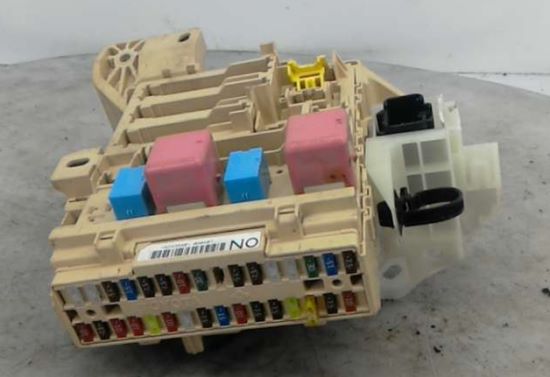
Photo - example.
| Diagram | ||
|---|---|---|

|
||
| No. | Decoding | A |
| 1 | Rear right power window | 25 |
| 2 | Rear left power window | 25 |
| 3 | Spare | 7.5 |
| 4 | Fog lamps | 15 |
| 5 | On-board diagnostic system | 7.5 |
| 6 | Spare | 7.5 |
| 7 | Bollard signals, gear lock system, fuel injection system, ABS, VSC, TRC, VA, throttle control system, body ECU | 10 |
| 8 | Spare | 30 |
| 9 | Starter, fuel injection system | 7.5 |
| 10 | Air conditioning system | 7.5 |
| 11 | Power windows | 25 |
| 12 | Body electrical control unit | 25 |
| 13 | Electric sunroof | 30 |
| 14 | Rear lights, license plate lights, parking lights | 15 |
| 15 | Heated seats, alarm, air conditioning, audio system, clock, glove box lamp, instrument cluster lamps, steering wheel switches | 7.5 |
| 16 | Body ECU, electrically operated sunroof, electric radiator fan, auto-dimming interior mirror, windscreen wiper and washer | 10 |
| 17 | ABS, VSC, TRC, VA, gear lock, cruise control, automatic transmission | 7.5 |
| 18 | Air conditioning system, heated rear window | 10 |
| 19 | Windshield wiper and commoner | 10 |
| 20 | Heated seats | 20 |
| 21 | Hazard warning lamps, rear code lamps, battery charging system | 10 |
| 22 | Windshield wiper and washer | 25 |
| 23 | Electro-corrector headlamps | 7.5 |
| 24 | Fuel injection system, starter | 15 |
| 25 | Immobilizer, injection system, SRS, throttle | 10 |
| 26 | Instrumentation, multifunction display, clock | 7.5 |
| 27 | Clock, body control unit, gear lock, outside mirrors | 7.5 |
| 28 | Electrical socket, cigarette lighter fuse Camry 40 | 20 |
| 29 | ||
| 30 | Audio system | 7.5 |
| 31 | Heated exterior mirrors | 10 |
| 32 | Power windows | 30 |
| 33 | Power seat adjustment | 30 |
| Elements on the back of the block | ||
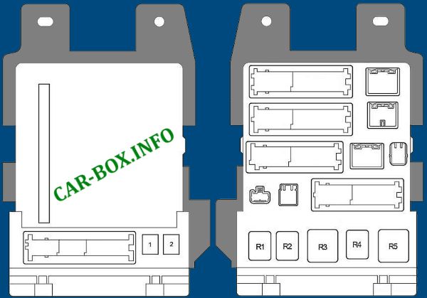
|
||
| No. | Appointment | A |
| R1 | Fog lamps | |
| R2 | Parking lamps | |
| R3 | Auxiliary relay | |
| R4 | Power Windows | |
| R5 | Ignition | |
| 1 | Power seats | 30 |
| 2 | Power Windows | 30 |
In the engine compartment
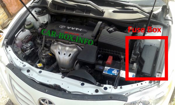
The fuse box is located on the right near the battery.

General view.
| Diagram | ||
|---|---|---|
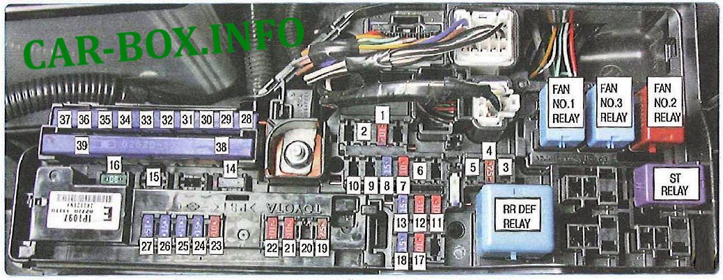
|
||
| No. | A | Description |
| 1 | 10 | Rear fog lamps |
| 2 | 15 | Spare |
| 3 | 7.5 | |
| 4 | 7.5 | Battery charging system |
| 5 | 7.5 | Spare |
| 6 | 10 | |
| 7 | 10 | Throttle control system |
| 8 | 15 | Direction indicators |
| 9 | 20 | Fuel injection system, starter, immobilizer, SRS passive safety system, throttle control system, instrumentation, multifunction display, clock |
| 10 | 20 | Spare |
| 11 | 10 | Instrumentation, vanity mirror illumination, trunk illumination, ignition switch illumination, door illumination, interior lamps, reading lamp, clock |
| 12 | 10 | Body ECM, VSC |
| 13 | 15 | Audio system |
| 14 | 25 | Body electrical control unit |
| 15 | 25 | Spare |
| 16 | 30 | Fuel injection system, throttle control system |
| 17 | 10 | Fuel injection system |
| 18 | 15 | |
| 19 | 7.5 | Sound signal (horn) |
| 20 | 20 | Fuel injection system |
| 21 | 10 | Instrumentation |
| 22 | 10 | Immobilizer, fuel injection system, throttle control system |
| 23 | 10 | Sound signal (horn) |
| 24 | 15 | Right headlamp (low beam), headlamps corrector |
| 25 | 15 | Left headlamp (low beam) |
| 26 | 15 | Right headlamp (high beam) |
| 27 | 15 | Left headlamp (high beam) |
| 28 | 50 | Air conditioning system |
| 29 | 50 | ABS, VSC, TRC, BA systems |
| 30 | 50 | Radiator fan |
| 31 | 30 | ABS systems, VSC, TRC, BA |
| 32 | 50 | Heated rear window, heated outside rear-view mirrors |
| 33 | 30 | Spare |
| 34 | 30 | headlight washer |
| 35 | 40 | Radiator fan |
| 36 | 40 | |
| 37 | 30 | Spare |
| 38 | 120 | Fog lamps, battery charging system, throttle control system, direction indicators, fuel injection system, starter, instrumentation, multifunction display, clock, immobilizer, SRS passive safety system, vanity mirror lamp, trunk lamps, ignition switch light, door lamps, interior lamps, reading lamp, body electrical control unit, audio system, horn, headlamps, headlamp corrector, air conditioning system, ABS, VSC, TRC, BA, heated rear window, heated outside mirrors, headlamp washers, radiator fan |
| 39 | 30 | Starter |
| ST RELAY- | Starter relay | |
| RR DEF RELAY- |
Heated rear window relay |
|
| FAN NO.1 RELAY- |
Radiator fan relay |
|
| FAN NO.2 RELAY- | ||
| FAN NO.3 RELAY- | ||
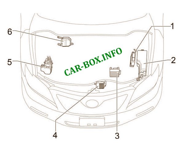
Car body
General layout of electronic modules.
| No. | Component |
| In the passenger compartment | |

|
|
| 1 | Fuse box |
| 2 | Body electrical control unit |
| 3 | Turn lamps relay (alarm) |
| 4 | Distribution module No. 3 |
| 5 |
|
| 6 | Distribution module (CAN) |
| 7 | Distribution module No. 4 |
| 8 | Air conditioner amplifier |
| 9 | Certification module |
| 10 | Tire pressure monitoring module |
| 11 | Central airbag module |
| 12 | Audio amplifier |
| 13 | Gearbox selector lock module |
| 14 | Key signal amplifier |
| 15 | Steering wheel lock module |
| In the engine compartment | |
|
|
| 1 | Engine control unit (2AZ-FE) |
| 2 | Main fuse box |
| 3 | Gearbox control unit |
| 4 | Fan control module |
| 5 | Skid Control |
| 6 | Engine control unit (2GR-FE) |
