The 4th generation Volkswagen Polo was produced in 2001, 2002, 2003, 2004, 2005, 2006, 2007, 2008 and 2009 with sedan and hatchback bodies. In 2005, the car was updated and an additional model made in the off-road style of the Cross Polo was introduced. In this publication, we will show where all the electronic control units in the Volkswagen Polo 4 are located.
Separately, we will highlight the purpose of fuses and relays with block diagrams in which they are located.
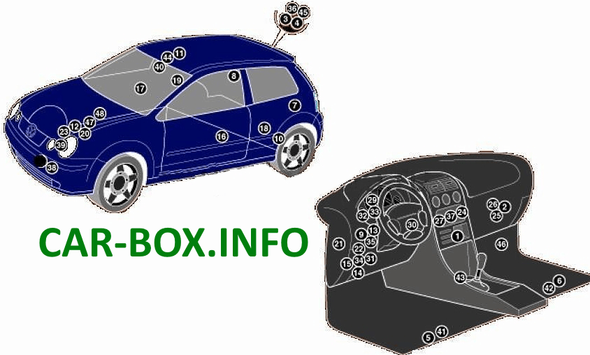
General layout
Arrangement of electronic control units.
|
|
| № | Control unit |
| 1 | Air conditioning control unit - in the heater control panel |
| 2 | A / C / Heater Fan Motor Control Unit (with automatic temperature control) - Fan Unit |
| 3 | Antenna signal amplifier (audio system) - in the audio system antenna |
| 4 | Antenna signal amplifier (navigation system) -in the antenna of the audio system |
| 5 | Side impact sensor, driver's side - under the front seat |
| 6 | Side gift sensor, on the passenger side - under the front seat |
| 7 | Side impact sensor, rear left (left curtain airbag) - luggage compartment, behind the left trim panel |
| 8 | Side impact sensor, rear right (right curtain airbag) - luggage compartment, behind the right trim panel |
| 9 | Anti-theft system control unit -in multifunction control unit 2 |
| 10 | Anti-theft alarm sound - behind the rear left wheel arch trim |
| 11 | Volume change sensor (anti-theft system) - front interior lamp |
| 12 | Accumulator battery |
| 13 | Central locking control unit - in multifunction control unit 2 |
| 14 | Diagnostic connector (DLC) |
| 15 | Diagnostic unit - in multifunction control unit 1 |
| 16 | Door function control unit, front left (central locking / door mirror / power window) |
| 17 | Door function control unit, front right (central locking / door mirror / power window) |
| 18 | Door function control unit, rear left (central locking / power window) |
| 19 | Door function control unit, rear right (central locking / power window) |
| 20 | Cooling Fan Motor Control Unit - with A / C-AXU |
| 21 | Fuse / relay box dashboard 1 |
| 22 | Fuse / relay box dashboard 2 |
| 23 | Fuse / Relay Box, Engine Compartment - Above Battery |
| 24 | Additional fuse (5A / 7.5A / 10A) - at the rear of the audio system / navigation system control unit |
| 25 | Heater fan motor resistor (manual temperature control) -fan unit |
| 26 | Heater blower motor resistor (automatic temperature control) - in the air conditioning / heater blower motor control unit |
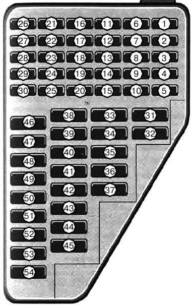
Fuse box
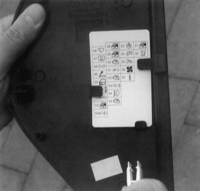
The fuse box is located in the passenger compartment, at the end of the dashboard on the driver's side and is covered by a protective cover. Check the current fuse designation and numbers on the inside of the cover.
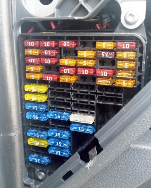
Photo - example.
| Diagram | |
|---|---|
|
|
| № | Amps & Description |
| 1 | 10A Wiper, rear window washer |
| 2 | 5A Rheostat for instrument cluster illumination, license plate lamp |
| 3 | 5A Rear fog lamps |
| 4 | 5A Brake light switch (brake pedal position sensor), cruise control, engine management |
| 5 | 5A Engine management, exhaust gas circulation |
| 6 | 5A Headlight range control |
| 7 | 5A Engine management, power steering |
| 8 | 5A Heated door mirrors |
| 9 | 10A Engine management |
| 10 | 5A S-pin |
| 11 | 5A Electric door mirror heater |
| 12 | 5A Lamps front right side marker, rear right side marker |
| 13 | 5A Lamps, front left, rear left |
| 14 | 10A Engine management system, intake manifold heater |
| 15 | 10A automatic transmission |
| 16 | 10A Wiper, windshield washer |
| 17 | 5A Engine management |
| 18 | 5A Air conditioning system, air recirculation system (air conditioning / heater), anti-theft system, interior rearview mirror with auto-dimming, cooling fan motor control unit, instrument cluster, navigation system |
| 19 | 10A Heated windscreen washer nozzles, reversing lights |
| 20 | 5A Instrument Cluster |
| 21 | 10A Right headlight-high beam |
| 22 | 10A LH headlamp - high beam |
| 23 | 10A Anti-lock braking system, stability control system |
| 24 | 10A Multifunction control unit 1 |
| 25 | 10A Engine management |
| 26 | 10A Stop lights |
| 27 | 5A Anti-lock braking system (with ESP), instrument cluster |
| 28 | 10A Interior lamps |
| 29 | 5A Air conditioning system, diagnostic connector (DLC), telephone |
| 30 | 5A Multifunction control unit 1, automatic transmission selector lock system, rain sensor (windshield wiper) |
| 31 | 25A Front left door power window motor |
| 32 | 15A Heated seats |
| 33 | 15A Anti-theft alarm horn |
| 34 | 15A Accessory power connector |
| 35 | 20A Hatch |
| 36 | 25A Air conditioner / heater blower motor |
| 37 | 15А20А Ignition coil (s), ignition system switch (s) |
| 38 | 25A Rear left door power window motor |
| 39 | 25A Front Right Door Window Regulator Motor |
| 40 | 10A / 30A Engine management |
| 41 | 15A Fuel pump, fuel supply pump - petrol / TDI |
| 42 | 20A Engine management - AXU |
| 43 | 15A RH headlight-low beam, headlight range control |
| 44 | 15A Fog lights |
| 45 | 15A Engine management - AUB |
| 46 | 20A Wiper, windshield washer |
| 47 | 20A Heated rear window (^ 02/04) |
| 48 | 15A Direction indicators, hazard warning lights |
| 49 | 15A Cigarette lighter |
| 50 | 15A Multifunctional control unit 2, anti-theft system, central locking |
| 51 | 15A Audio system, navigation system |
| 52 | 20A Horn, wiper, windshield washer |
| 53 | 25A Rear right door power window motor |
| 54 | 15A Left headlight - low beam, headlight range control |
The fuse is responsible for the cigarette lighter 49 at 15A.
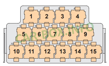
Relay box
The relay box is located behind the instrument panel trim on the driver's side. The Polo has a single relay box with the same type of sockets.
| Diagram | |
|---|---|
|
|
| № | Description |
| 1 | Reserve |
| 2 | Relay in the power supply circuit of the Motronic system |
| 3 | (100) Glow plug relay |
| 4 | (53) Fuel supply pump relay (TDI) |
| 5 | (449) Relay for turning on the door marker lamp, door opening lamps |
| 6 | (53) Headlight washer pump relay |
| 7 | (126) Starter interlock relay |
| 8 | (53) Auxiliary heater relay 1, low power |
| 9 | (100) Auxiliary heater relay 2, high power (diesel) |
| 10 | (53/429) Engine management system relay (petrol, except AXU) |
| 11 | (18) Ignition auxiliary circuits relay, X terminal unload relay |
| 12 | (404) Start relay (fuel system) (petrol, except AXU) |
| 13 | (167) Fuel pump relay (petrol, except AXU) |
| 14 | Auxiliary heater fuse box |
| 15 | (109) Engine management system relay (diesel) |
Some fuses can also be mounted in this unit, for example, an additional 40A heater.
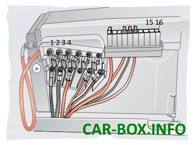
Battery box
It is located on the battery cover. The number of fuses included in it depends on the specific vehicle configuration. The block holders can hold a maximum of 6 blade fuses and 10 blade fuses. The connection to the positive terminal is made by means of a wire with a terminal lug and a screw. Fuses protect individual on-board circuits against overloading directly at the battery output.
| Diagram | |
|---|---|
|
|
| № | Amps & Description |
| 1 | 110A Generator |
| 2 | 110 Salon, ignition lock |
| 3 | 50A Power steering |
| 4 | 50A Engine management system relay (AXU), exhaust air pump |
| 5 | 40A Cooling fan motor |
| 6 | 40A Anti-lock braking system (ABS) |
| 7 | 40A Anti-lock braking system (ABS) |
| 8 | 30A Cooling fan motor |
| 9 | Reserve |
| 10 | 5A Multifunction control unit 1 |
| 11 | 5A Air conditioning, cooling fan motor control unit |
| 12 | Reserve |
| 13 | 5A automatic transmission |
| 14 | Reserve |
| 15 | Reserve |
| 16 | Reserve |

نشكركم كان مفيدا
Thank you, that was helpful
محتوى تعليمي ممتاز شكرا لكم