Volkswagen Polo 5 th generation in the back of a hatchback was made in 2009, 2010, 2011, 2012, 2013, 2014, 2015, 2016 and 2017, 2018 respectively.
In this publication you will find information on the location of all electronic control units, as well as a description of the purpose of fuses and relays in the 5th generation Volkswagen Polo hatchback . The fuse responsible for the “Cigarette lighter” is highlighted in bold.
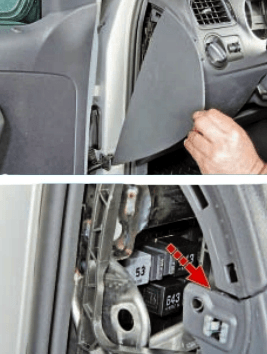
In the passenger compartment
Fuse box
Located under the steering column, behind the protective cover.
| Diagram | |
|---|---|

|
|
| № | Amps & Description |
| 1 | Not used |
| 2 | 10A Steering column switch block, Rear window wiper motor, Windscreen and rear window washer pump |
| 3 | 5 / 7,5A Fuel pump relay, Engine control unit, Ignition and starter switch |
| 4 | 2 / 7.5A Steering column switch block, Multifunction steering wheel control unit |
| 5 | Not used |
| 6 | 5A Instrument cluster control unit |
| 7 | 5 / 15A Headlight range control, License plate light, Switch and instrument cluster backlight brightness control |
| 8 | 10A Injectors |
| 9 | 5 / 7.5A ABS control unit, ASR and ESP deactivation button, Steering column switch block, Tire pressure indicator button |
| 10 | 5 / 7.5A Speed sensor, Onboard supply control unit, Radio |
| 11 | 5 / 10A Headlight range control, Steering column switch block, Instrument cluster control unit |
| 12 | 5 / 7.5 Exterior mirror adjuster, Exterior mirrors |
| 13 | 10 / 15A Automatic gearbox control unit, Multi-function switch, Automatic gearbox selector |
| 14 | 5 / 15A Airbag control unit, control lamp off. PP airbags |
| 15 | Not used |
| 16 | 5 / 10A Parking aid control unit |
| 17 | 10A Lambda probe heating element, Canister solenoid valve 1, Windscreen and rear window washer pump |
| 18 | 5 / 7.5A Instrument Cluster Control Unit, Right Fog Lamp Lamp |
| 19 | 5 / 7.5А Side light relay, Head unit, Ignition and starter switch |
| 20 | 5 / 10A Instrument Cluster Control Unit, Steering Column Switch Block, Main Relay |
| 21 | 10 / 15A Onboard supply control unit - courtesy lights |
| 22 | 5 / 10A Diagnostic connector, Air conditioning control unit, Climatronic control unit, Ignition key removal lock solenoid, Rain and light sensor, Side light relay, Heated outside mirror relay |
| 23 | 7.5 / 10A Onboard supply control unit, Engine control unit, Automatic gearbox control unit, Automatic gearbox selector, Rain sensor |
| 24 | 15A Heated outside mirrors, Heated outside mirror relay |
| 25 | 5 / 15A High pressure sensor, Air conditioning relay, Air conditioning control unit, Diagnostic socket, Electrochromic interior mirror, Climatronic control unit |
| 26 | 5 / 7,5 / 20A Power steering control unit, Air mass meter, Air conditioning relay |
| 27 | 5 / 15A Reversing light switch |
| 28 | 15A Lambda probe, Cylinder injectors, Glow plug control unit |
| 29 | 10/15 / 20A Pressure and fuel metering regulator, Ignition coils |
| 30 | 10A Coolant circulation pump 2, Exhaust gas recirculation cooler changeover valve, Charge pressure limiting solenoid valve |
| 31 | 10 / 15A Pressure Fuel Relay, Glow Plug Control Unit, Cylinder Injectors, Ignition Coils |
| 32 | 30A Engine control unit |
| 33 | 5 / 10A Clutch pedal switch, Brake light switch, Radiator fan control unit, Air conditioning relay |
| 34 | 7.5A Right high beam headlight bulb, Left high beam headlight bulb, Instrument cluster control unit |
| 35 | 10A Engine control unit |
| 36 | 15 / 20A Booster fuel pump, Relay for supplying fuel in the pressure line, Relay for fuel pump |
| 37 | 25A Seat heating control unit |
| 38 | 7.5 / 30A Lamp for left headlight high beam, Control unit in instrument cluster, Control unit for automatic transmission |
| 39 | 10 / 15A Lamp of the right headlight low beam |
| 40 | 30A Supply fan switch, Supply fan control unit |
| 41 | 10A Rear window wiper motor |
| 42 | 15 / 20A Cigarette lighter |
| 43 | 15 / 20A Onboard supply control unit, Turning lamps, Stop signals |
| 44 | 5 / 10A Alarm Siren, Burglar Alarm Sensor |
| 45 | 15 / 30A Head unit, Multimedia system control unit |
| 46 | 20 / 30A Horn, Headlight washers |
| 47 | 20 / 30A Wiper motor |
| 48 | 25 / 30A Central locking, Electric motor for locking the fuel filler flap |
| 49 | 5 / 15A Reversing lamps |
| 50 | 25 / 30A Driver's door control unit, Front left power window switch |
| 51 | 25 / 30A Front passenger door control unit, Power window switch on the front passenger door |
| 52 | 30A Rear door and power window control unit |
| 53 | 30A Rear window heating element |
| 54 | 15 / 20A Fog lights |
| 55 | 15A Ignition coils |
| 56 | 15A Daytime running lights |
| 57 | 5 / 7.5A Front left side light bulb, Rear light, left |
| 58 | 5 / 7.5A Front right side light bulb, Rear light, right, Brake servo vacuum pump |
| 59 | 10 / 15A Lamp of the left headlight low beam |
| 60 | 15A DRL, Audio system |
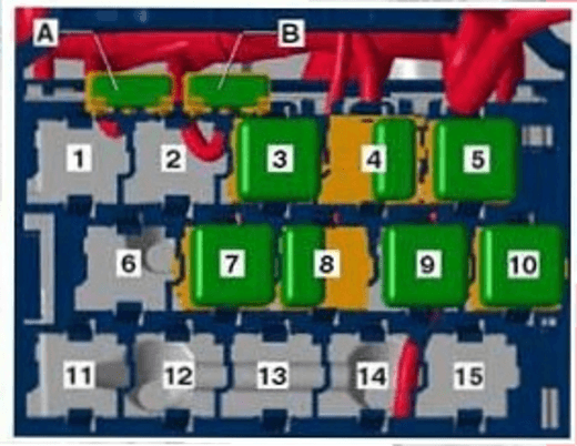
Relay box
This unit is located under the dashboard on the driver's side.
| Diagram | ||
|---|---|---|
|
||
| № | Description | |
| 1 | Not used | |
| 2 | Not used | |
| 3 | Not used | |
| 4 |
|
|
| 5 |
|
|
| 6 |
|
|
| 7 |
|
|
| 8 |
|
|
| 9 |
|
|
| 10 | Relay for unloading contact X | |
| 11 | Not used | |
| 12 | Not used | |
| 13 | Fuel pump relay (left, from August 2012) | |
| 14 | Not used | |
| 15 | Air conditioner relay (from August 2012) | |
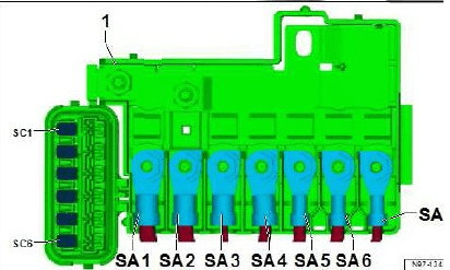
In the engine compartment

Located in the cover on the battery.
| Diagram | |
|---|---|
|
|
| № | Amps & Description |
| SA1 | 150A Generator |
| SA2 | Not used |
| SA3 | 110A Ignition and starter switch, Lighting switch, Block of understeering switches, Relay for unloading contact, Relay for fuel pump, Relay for dipped beam, Fuse 20 in the fuse box, Relay for side lights, Power relay for cl. 30, Fuse 3. |
| SA4 | 50A Power steering control unit |
| SA5 | 40A Control unit AB |
| SA6 | 40A Radiator Fan Control Unit, Radiator Fan |
| SA7 | 50A Glow plug control unit |
| SC1 | 25A ABS control unit |
| SC2 | 30A Radiator Fan Control Module, Radiator Fan, Radiator Fan Thermal Switch |
| SC3 | Not used |
| SC4 | 10A ABS control unit |
| SC5 | 5 / 10A Onboard supply control unit |
| SC6 | 25A Automatic gearbox control unit |
