
The Volkswagen Sharan was produced across two generations from 1995 to the present. First-generation models were manufactured from 1996 through 2009. During this production run, the vehicle received two facelifts, resulting in several distinct fuse and relay panel configurations. This document details the locations of all electronic control units (ECUs) and provides comprehensive fuse and relay assignment diagrams for the first-generation VW Sharan (chassis code 7M; B-VX62 platform). The fuse responsible for the “Cigarette lighter” is highlighted in bold.

The quantity, design, and function of components may vary depending on the model year, equipment specification, and target market. Two primary variations are presented below: Type 1 applies primarily to pre-1998 models, while Type 2 applies to post-1998 models.
General Layout
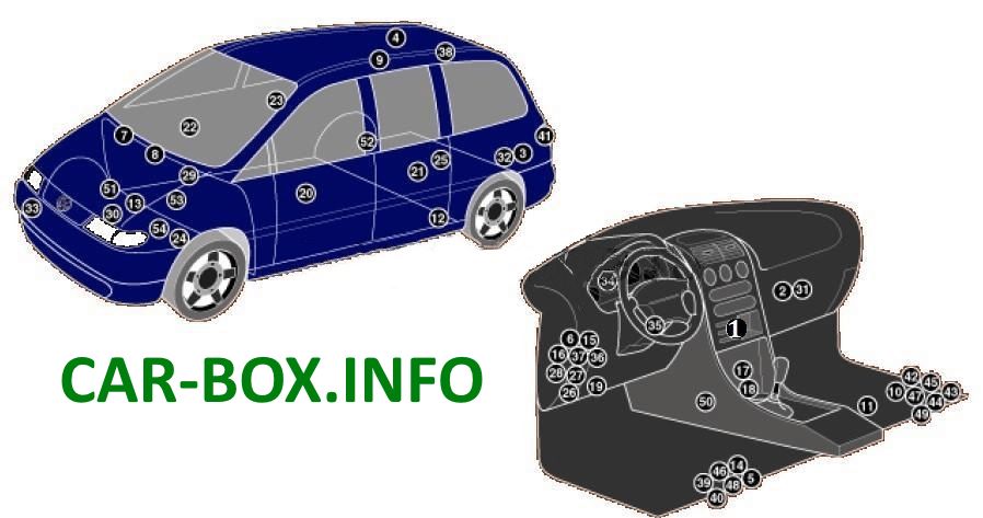
Location of Electronic Control Units (ECUs).
 |
|
| 1 | Air conditioning electronic control unit |
| 2 | Front heater/air conditioning blower motor control unit (automatic climate control) |
| 3 | Rear heater/air conditioning blower motor control unit (automatic climate control) |
| 4 | Antenna amplifier — behind roof headliner |
| 5 | Anti-theft alarm/central locking control unit — under driver seat (up to 08/97) |
| 6 | Anti-theft alarm control unit — integrated in multifunction control unit (from 09/97) |
| 7 | Anti-theft alarm horn — intake system resonator (up to 04/00) |
| 8 | Anti-theft alarm horn — intake system resonator (from 05/00) |
| 9 | Audio system antenna — right rear side window |
| 10 | Auxiliary battery — under passenger seat (if equipped) |
| 11 | Auxiliary battery relay (from 11/98) — under front right seat |
| 12 | Auxiliary heater control unit |
| 13 | Main battery |
| 14 | Central locking control unit — inside anti-theft control unit under driver seat (up to 08/97) |
| 15 | Central locking control unit — integrated in multifunction control unit (from 09/97) |
| 16 | Anti-theft alarm control unit — dashboard fuse/relay box 2 |
| 17 | Cruise control module (CCM) |
| 18 | Data link connector (DLC) — under front ashtray (up to 04/00) |
| 19 | Data link connector (DLC) — (from 05/00) |
| 20 | Front left power window control unit — door |
| 21 | Rear left power window control unit — door |
| 22 | Front right power window control unit — door |
| 23 | Rear right power window control unit — door |
| 24 | Radiator cooling fan control unit |
| 25 | Four-wheel drive (4WD) control unit — on transfer clutch |
| 26 | Dashboard fuse/relay box 1 — integrated in multifunction control unit (from 09/97) |
| 27 | Dashboard fuse/relay box 2 |
| 28 | Dashboard fuse/relay box 3 |
| 29 | Engine compartment fuse/relay box 1 |
| 30 | Engine compartment fuse/relay box 2 |
| 31 | Front heater blower motor resistor (manual climate control) |
| 32 | Rear heater blower motor resistor (manual climate control) |
| 33 | Horns — behind front bumper |
| 34 | Immobilizer control unit — behind instrument cluster |
| 35 | Immobilizer antenna ring — adjacent to ignition switch |
| 36 | Turn signal relay — integrated in multifunction control unit |
| 37 | Multifunction control unit — inside dashboard fuse/relay box 1 (functions: heated windshield/rear window, front/rear wipers, turn signals, hazard lights, interior lighting, power windows, central locking, keyless entry, anti-theft system) |
| 38 | Navigation and telephone antenna |
| 39 | Park assist control unit — under driver seat |
| 40 | Front park assist buzzer — under driver seat |
| 41 | Rear park assist buzzer — behind tail light cover |
| 42 | Auxiliary fuse (30 A / 40 A), auxiliary battery — under front right seat |
| 43 | Auxiliary fuse (30 A), auxiliary heater (from 09/01) — under front right seat |
| 44 | Auxiliary fuse (15 A), 12 V power socket 1 (01/98–05/00) — under front right seat |
| 45 | Auxiliary fuse (15 A), 12 V power socket 2 (01/98–05/00) — under front right seat |
| 46 | Driver seat heating control unit — under driver seat |
| 47 | Passenger seat heating control unit — under passenger seat |
| 48 | Driver side-impact sensor — under driver seat |
| 49 | Passenger side-impact sensor — under passenger seat |
| 50 | Airbag control unit (SRS) |
| 51 | Front ride height sensor — headlight leveling system (on anti-roll bar) |
| 52 | Rear ride height sensor — headlight leveling system (on right rear axle shaft) |
| 53 | Transmission control unit (TCU) — engine compartment, left side |
| 54 | Vehicle speed sensor (VSS) — on transmission |
In the Passenger Compartment
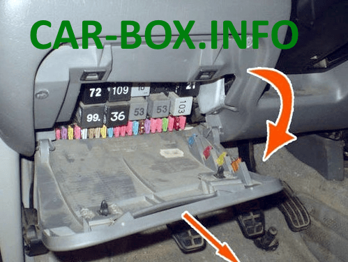
The main fuse and relay panels are located on the left side of the dashboard behind the access panel.
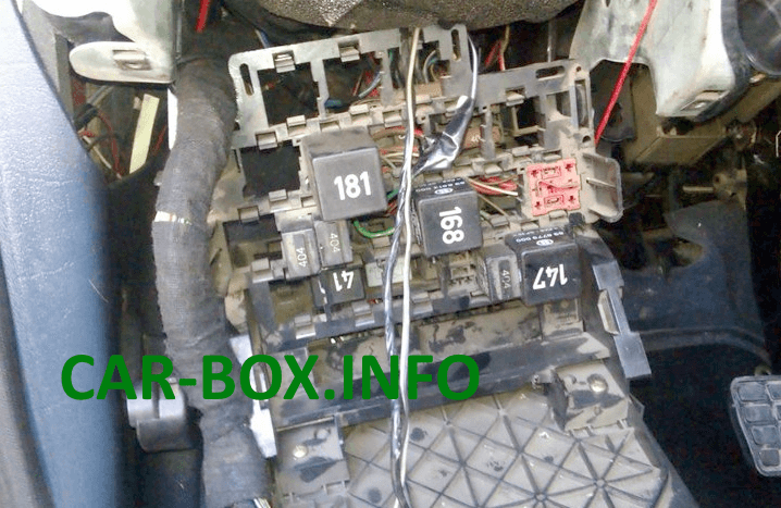
An auxiliary relay panel is mounted behind the main panel.
Fuse Box
Type 1
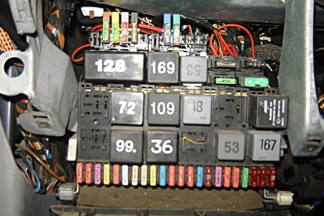
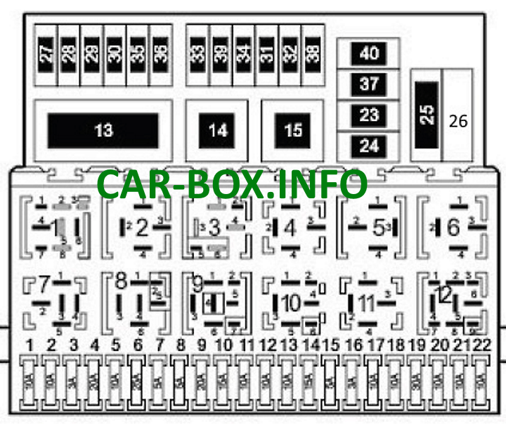
Overview.
| Diagram | |
|---|---|
 |
|
| No. | Description |
| 1 | - |
| 2 | (72) Rear wiper/washer relay |
| 3 | (30/109) Engine management relay — ADY / AKT / 1Z / AHU / AFN |
| 4 | (18) Auxiliary ignition circuit relay |
| 5 | - |
| 6 | (21/22) Hazard flasher relay |
| 7 | (95) Headlamp washer pump relay |
| 8 | (19/99) Intermittent windshield wiper relay |
| 9 | (36) Lights-on warning buzzer |
| 10 | (53) Front fog light relay |
| 11 | (53) Horn relay |
| 12 | (167) Fuel pump relay — AAA / ADY / AKT |
| 13 | (128) Daytime running light (DRL) relay |
| 14 | (169) Heated rear window relay |
| 15 | (53/204) Windshield wiper relay |
| F1 | (10 A) Left low-beam headlight, left headlight leveling |
| F2 | (10 A) Right low-beam headlight, right headlight leveling |
| F3 | (3 A) License plate lights |
| F4 | (20 A) Rear wiper/washer, daytime running lights (DRL), rear climate/heater blower motor |
| F5 | (10 A) Windshield wiper/washer, heated washer nozzles |
| F6 | (25 A) A/C system, front blower motor |
| F7 | (5 A) Right parking/tail light, engine compartment light |
| F8 | (5 A) Left parking/tail lights |
| F9 | (20 A) Heated rear window, rear defroster relay |
| F10 | (15 A) Rear fog lights |
| F11 | (10 A) Left high-beam headlight |
| F12 | (10 A) Right high-beam headlight |
| F13 | (10 A) Horn |
| F14 | (15 A) Reversing lights, cruise control, heated windshield relay, central locking, power windows, power mirrors, heated seats, air conditioning, auxiliary heater, 4WD system, automatic transmission (AT) selector illumination |
| F15 | (5 A / 10 A) Engine control unit (ECU), immobilizer, gear selector illumination, crankcase breather heater, EGR valve, EVAP purge valve |
| F16 | (3 A) Clock, front interior light, glove box light, heated rear window relay, instrument cluster |
| F17 | (10 A) Turn signals |
| F18 | (10 A) Fuel pump, heated oxygen sensor (O2S) — AAA / ADY / AKT |
| F19 | (30 A) Radiator cooling fan control module, auxiliary coolant pump |
| F20 | (10 A) Brake light switch |
| F21 | (10 A) Instrument cluster, clock, audio head unit, CD changer, audio amplifier, interior lights, sunroof |
| F22 | (10 A) Air conditioning, data link connector (DLC) |
| F23 | (7.5 A) Radiator cooling fan control unit, auxiliary coolant pump, A/C compressor magnetic clutch |
| F24 | (30 A) Windshield wipers |
| F25 | (60 A) Diesel glow plugs |
| F26 | Reserved / Spare |
| F27 | (50 A) Heated windshield |
| F28 | (30 A) ABS control unit |
| F29 | (30 A) ABS control unit |
| F30 | (10 A) Central locking |
| F31 | (10 A) Central locking, anti-theft alarm horn |
| F32 | (10 A) Central locking, hazard lights (anti-theft system) |
| F33 | (25 A / 30 A) Auxiliary heater |
| F34 | (25 A) Rear climate/heater blower motor |
| F35 | (20 A) Cigarette lighter, trailer wiring socket, auxiliary power sockets |
| F36 | (10 A) Car phone |
| F37 | (30 A) Power windows |
| F38 | (20 A) Spare |
| F39 | (25 A) Front Climatronic control module |
| F40 | (5 A) Radiator fan relay (speeds 1 & 2) |
| In Type 1, fuse #35 (20 A) powers the cigarette lighter, while fuse #22 supplies auxiliary power sockets. | |
Type 2
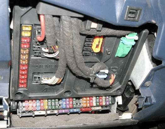
Overview.
| Diagram | |
|---|---|
 |
|
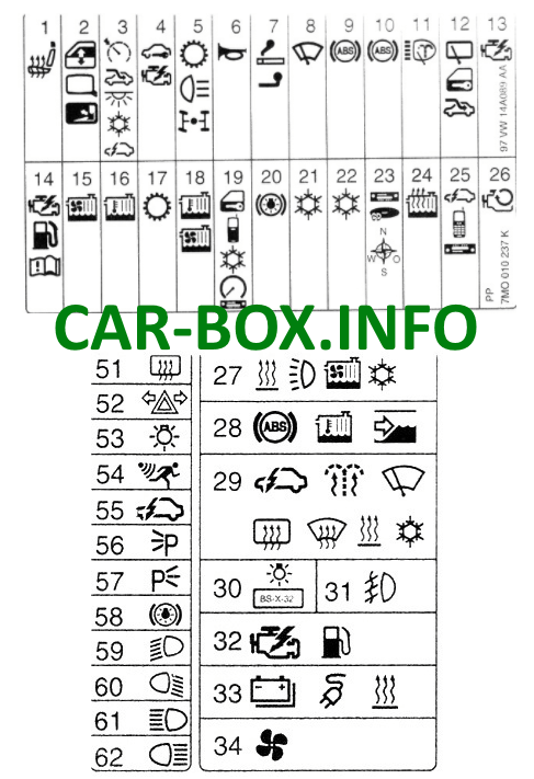
| No. | Rating & Description |
| 1 | (20 A) Heated seats |
| 2 | (10 A) Power windows, power mirrors |
| 3 | (5 A) Cruise control, sunroof, glove box light, clock, navigation system, air conditioning, auxiliary heater, multifunction control unit, trip computer |
| 4 | (10 A) Engine management (ECU), immobilizer, crankcase breather heater — AAA / AMY / ANU |
| 5 | (15 A) Reversing lights, automatic transmission (AT), AWD system |
| 6 | (10 A / 25 A) Horn / Alarm buzzer |
| 7 | (20 A) Cigarette lighter |
| 8 | (30 A) Windshield wipers and washer |
| 9 | (30 A) Anti-lock braking system (ABS) |
| 10 | (30 A) Anti-lock braking system (ABS) |
| 11 | (20 A) Headlight washers |
| 12 | (15 A) Sunroof, clock, multifunction control unit (central locking, rear window wiper/washer) |
| 13 | (3 A) Engine management (petrol) |
| 14 | (10 A / 20 A / 25 A / 30 A) Engine management (ECU) |
| 15 | (30 A) Radiator cooling fan — AAA / AFN / AHU |
| 16 | (15 A / 30 A) Radiator cooling fan (from 06/00) |
| 17 | (10 A) Automatic transmission control |
| 18 | (5 A / 10 A) Radiator cooling fan |
| 19 | (5 A) Central locking, car phone, air conditioning, instrument cluster, audio system, park assist (11/98–05/00), data link connector (DLC) |
| 20 | (10 A) Brake lights |
| 21 | (25 A / 30 A) Air conditioning system |
| 22 | (25 A / 30 A) Air conditioning system |
| 23 | (10 A) Audio head unit, CD changer, navigation system |
| 24 | (25 A) Auxiliary heater |
| 25 | (3 A) Multifunction control unit, car phone, audio system |
| 26 | (30 A) Starter inhibit relay / reversing light relay |
| 27 | (25 A) A/C system, auxiliary coolant pump |
| 28 | (10 A) Anti-lock braking system (ABS), auxiliary coolant pump, windshield wiper/washer |
| 29 | (5 A) Multifunction control unit, heated washer nozzles, windshield wiper (up to 10/98), heated windshield, heated rear window, auxiliary heater, heater blower motor (up to 10/98), air conditioning |
| 30 | (3 A) License plate lights |
| 31 | (15 A) Front fog lights |
| 32 | (3 A / 10 A) Engine management — ADY / AAA / AJH / AKT / ANU |
| 33 | (25 A) Trailer wiring socket, 12 V power socket, auxiliary battery |
| 34 | (25 A) Heating/ventilation system |
| 51 | (20 A) Heated rear window |
| 52 | (20 A) Turn signals |
| 53 | (10 A) Interior lights |
| 54 | (10 A) Anti-theft system |
| 55 | (5 A) Door entry lights, instrument cluster, anti-theft system, central locking, power windows |
| 56 | (5 A) Right side marker light, right tail light |
| 57 | (5 A) Left side marker light, left tail light |
| 58 | (10 A) Headlight leveling system |
| 59 | (10 A / 15 A) Left low-beam headlight |
| 60 | (10 A / 15 A) Right low-beam headlight |
| 61 | (10 A) Left high-beam headlight |
| 62 | (10 A) Right high-beam headlight |
Main Relay Panel
Located behind the main fuse panel.
| Diagram | |
|---|---|
| Type 1 | |
 |
|
| No. | Description |
| 1 | Diagnostic bus splitter |
| 2 | Terminal 15a power distribution junction |
| 3 | Terminal 58b illumination distribution junction |
| 4 | Speed signal distribution junction |
| 5 | Terminal 54 brake light signal distribution junction |
| 6 | Door contact switch junction |
| 18 | Audio speaker muting relay (car phone) |
| 19 | Daytime running light (DRL) relay (200) |
| - | Reserved / Spare |
| 31 | Rear vent window relay (149) |
| 22 | Heated windshield relay (170) |
| 23 | Unused |
| 24 | Power window relay (53) |
| 25 | Rear heater blower motor relay (94) |
| 26 | Seat belt warning relay |
| Type 2 | |
 |
|
| No. | Description |
| 1 | (361) Power folding mirror control unit |
| 2 | (361) Power folding mirror control unit |
| 3 | Audio/telephone speaker switching relay |
| 4 | (94) Heater blower motor relay (without A/C) |
| 5 | (53/131/181) Radiator cooling fan after-run relay |
| 6 | (175) Starter inhibit switch relay / reversing light relay |
| 7 | (106) Auxiliary heater relay (up to 04/98) |
| 8 | (95) Headlamp washer pump relay |
| 9 | (200) Daytime running light (DRL) relay (if equipped) |
| 10 | (53/404) Horn relay |
| 11 | (94) A/C compressor magnetic clutch relay — AFN / AHU |
| 12 | (168) A/C compressor magnetic clutch relay |
| 13 | (153) Diode module |
| 14 | (185) Immobilizer relay |
| 15 | (114) Heater blower motor relay — auxiliary heater (up to 04/98) |
| 16 | (149) Rear power vent window relay |
| 17 | (53/404) Auxiliary heater relay |
| 18 | (94) Auxiliary coolant pump relay |
| 19 | (109) Engine management relay |
Auxiliary Relay Panel
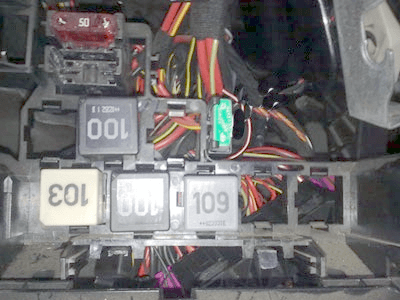 Accessing the auxiliary relay panel.
| Diagram | |
|---|---|
 |
|
| No. | Description |
| 20 | (404) Auxiliary heater control relay |
| 21 | (53) Windshield wiper motor relay / radiator fan relay (361) |
| 22 | (53) Secondary air injection pump relay / heated power mirror relay (404) |
| 23 | (100) Heated windshield relay |
| 24 | (167) Fuel pump relay / blower motor relay (53) |
| 25 | (53) Coolant glow plug heater relay |
| 26 | (100) Auxiliary ignition circuits relay |
| 27 | (114) A/C compressor magnetic clutch cut-off relay |
| 1 | 50 A — Heated windshield |
| 2 | 50 A — Secondary air injection pump; 25 A — Auxiliary heater |
| 3 | 25 A — Auxiliary heater |
| 4 | 30 A — Power window circuit breaker/fuse |
In the Engine Compartment
The main high-current fuse box is located adjacent to the battery, under a protective cover.
Main Pre-Fuse Box
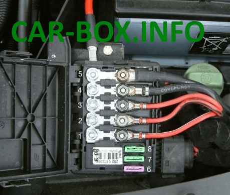
Layout Diagram
Fuse Assignments:
- 60 A — Glow plugs
- 40 A — Radiator cooling fan
- 40 A / 60 A — Radiator cooling fan
- 110 A — Passenger compartment power supply (terminal 30)
- 150 A — Alternator
- 3 A — Multifunction control unit
- 30 A — ABS system
- 30 A — ABS hydraulic pump
Auxiliary Fuse Box

An additional fuse box is fitted on select models.
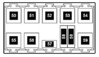
Relay Assignments:
- 50 — A/C cut-off relay (114)
- 51 — A/C shut-off relay (147)
- 52 — Reserved / Spare
- 53 — Reserved / Spare
- 54 — High-heat output coolant heater relay (103)
- 55 — Starter inhibit and reversing light relay (158)
- 56 — Secondary air injection pump relay (53)
- 57 — Secondary air injection pump relay
- 58 — Fuse for radiator fan and coolant glow plugs
- 59 — Low-heat output coolant heater relay (103)
