Most of the power supply circuits of the electrical equipment of the German minivan are protected by fuses. Headlights, fan motors, fuel pump and other powerful current consumers are connected via relays. Protective elements are installed in distribution boxes, which are located in the passenger compartment, under the hood and in the trunk.

In this article, we will take a detailed look at the fuse box diagrams for the Volkswagen Sharan (7N1) 2nd generation 2010, 2011, 2012, 2013, 2014, 2015 with gasoline and diesel engines.
In the engine compartment
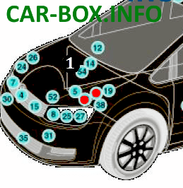
In the engine compartment there are two distribution boxes: one main, the second power. Marked in the photo above with red dots.
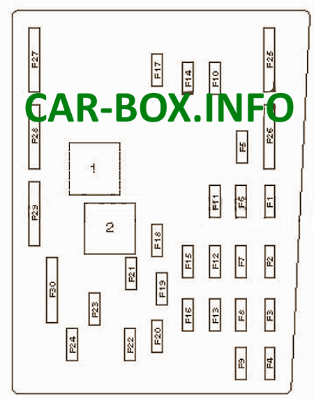
Fuse box
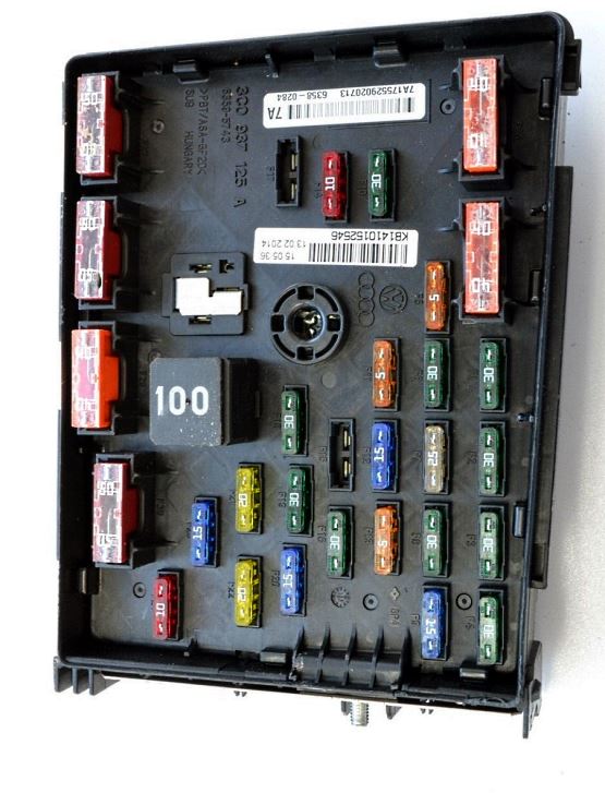
General view.
| Diagram | ||
|---|---|---|
|
||
| No. | Description | Amps |
| F1 | Voltage stabilizer block | 30 |
| F2 | Onboard supply control unit | 30 |
| F3 | ABS / ESP | 30 |
| F4 | Onboard supply control unit, supply circuit, left-hand lighting | 30 |
| F5 | battery control control unit | 5 |
| F6 | power circuit, lighting on the right | 30 |
| F7 | Dual Tone Horn Relay / Heated Windscreen Relay | 25 |
| F8 | Audio amplifier | 30 |
| F9 | Audio / navigation system | 20 |
| F10 | Engine management | 30 |
| F11 | Diagnostic unit | 5 |
| F12 | DSG mechatronic unit | 15 |
| F13 | Main relay | 5 |
| F14 | Engine management | 10/30 |
| F15 | - | |
| F16 | Engine management | 15/30 |
| F17 | 15/20 | |
| F18 | Fuel pump | 30 |
| F19 | Windshield wiper | 30 |
| F20 | Relay for auxiliary coolant pump | 15 |
| F21 | Additional heater | 20 |
| F22 | Headlight cleaning relay | 20/30 |
| F23 | 15 | |
| F24 | 10 | |
| F25 | ABS / ESP system | 40 |
| F26 | Supply fan control unit | 40 |
| F27 | Main ignition circuits | 50 |
| F28 | Glow plugs | 50 |
| F29 | 40 | |
| F30 | Auxiliary circuits | 50 |
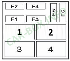
Power box
Diagram.

|
||
| No. | Description | Amps |
| 1 | Charging system, generator | 150/200 |
| 2 | Power steering | 80 |
| 3 | Cooling fan motor control unit | 80 |
| 4 | 80 | |
| 5 | 100 | |
| 6 | Heated windshield | 50 |
| 7 | Coolant heater | 70 |
| 8 | Thermo fuse 2. Rear right sliding door. Thermo fuse 1. Adjust the position of the driver's seat. Thermo fuse 1.Adjust the position of the front passenger seat |
60 |
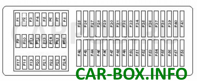
In the passenger compartment
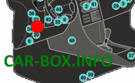
The distribution box is located on the driver's side, behind a plastic cover. Marked with a red dot in the photo above.
| Diagram | ||
|---|---|---|
|
||
| No. | Description | Amps |
| F4 | Starter relay | 10 |
| F5 | Suspension control system | 10 |
| F9 | SRS | 7.5 |
| F10 | Special vehicle equipment | 5 |
| F11 | 4WD control system | 10 |
| F12 | Xenon headlight (left) | 10 |
| F13 | 5 | |
| F14 | 7.5 | |
| F15 | 10 | |
| F16 | Xenon headlight (right) | 10 |
| F17 | Telephone | 5 |
| F18 | Special vehicle equipment | 7.5 |
| F20 | ABS / ESP | 5 |
| F21 | Air conditioner / heater | 5 |
| F24 | Remote control system for central locking and engine start | 7.5 |
| F26 | air conditioner / heater | 5 |
| F28 | Rear window wiper motor | 10/15 |
| F36 | Parking brake | 30 |
| F37 | 10/25 | |
| F38 | 10/30 | |
| F39 | Steering column electronics control unit | 7.5 |
| F40 | Multimedia system | 5 |
| F41 | Instrument cluster | 5 |
| F42 | Suspension control system | 15 |
| F43 | Power seat | 30 |
| F44 | 25 | |
| F45 | 30 | |
| F46 | 30 | |
| F47 | 10 | |
| F48 | 15 | |
| F49 | Parking brake | 30 |
| F50 | 30 | |
| F51 | Seat heater | 30 |
| F52 | 20/30 | |
| F53 | Accessory power connector | 30 |
| F54 | Steering column lock | 10 |
| F55 | Trailer electrical connector | 25 |
| F56 | Trailer control unit | 30 |
| F57 | Two-channel radio | 10 |
| F58 | Special vehicle equipment | 25 |
In the trunk
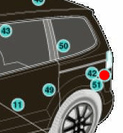
The location of the luggage fuse box is marked in the photo with a red dot
| Diagram | ||
|---|---|---|
|
||
| No. | Appointment | Amps |
| F1 | Left electrically operated sliding door | 40 |
| F2 | Rear door open / close drive control unit | 30 |
| F3 | Trailer control unit | 30 |
| F4 | 30 | |
| 1 | Trailer connector power relay | |
