Volkswagen Touareg is a mid-size crossover that has been produced in 3 generations from 2002 to the present with both gasoline and diesel engines. Years of production of the first generation: 2003, 2004, 2005, 2006, 2007, 2008, 2009 and 2010. During this time, the car received a facelift. The 2nd generation was produced in 2010, 2011, 2012, 2013, 2014, 2015, 2016, 2017, 2018. After that, the third generation of Touareg entered the assembly lines of the Volkswagen concern. In our material you will find a description of fuses and relays Volkswagen Touareg 2st (NF) generation with photos and block diagrams in which they are located. The fuse responsible for the “Cigarette lighter” is highlighted in bold.

The purpose of the elements in your blocks may differ from the one presented and depends on the year of manufacture and the level of electrical equipment of the car.
In the passenger compartment
On the left side

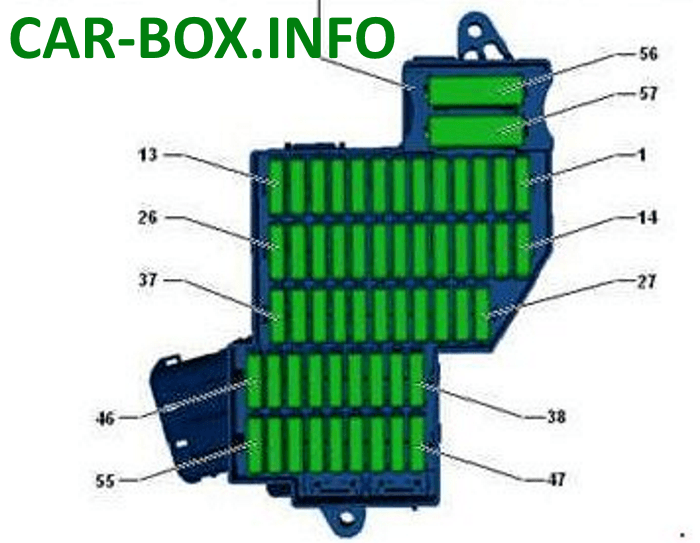
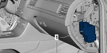
Located on the left side of the dashboard.
| Diagram | |
|---|---|
|
|
| № | Amps / Description |
| 1 | 25A Driver's seat adjustment and ventilation control unit |
| 2 | 30A heater control unit |
| 3 | 15 / 20A Signal |
| 4 | 30A Wiper motor |
| 5 | 30A Sliding sunroof control unit |
| 6 | 15/30 Backrest release control unit |
| 7 | 15A Electrically adjustable steering column control unit |
| 8 | 5 / 10A Tire pressure monitor control unit, Steering column control unit |
| 9 | 5A Light switch, Rain sensor, Front roof module, Tire pressure monitoring system control unit |
| 10 | 30A sunroof control unit |
| 11 | 10 / 15A Steering wheel heater, Steering column control unit |
| 12 | Not used |
| 13 | Not used |
| 14 | 30A Onboard supply control unit |
| 15 | 25 / 30A Onboard supply control unit |
| 16 | 30A Driver door control unit |
| 17 | 5 / 10A Interior sensor, Alarm siren, Hood limit switch |
| 18 | 30A Onboard supply control unit |
| 19 | 10A Engine control unit |
| 20 | 30A Onboard supply control unit, driver and passenger seat heating element |
| 21 | 10A Residual heat battery relay |
| 22 | 30A Onboard supply control unit |
| 23 | 7.5A Diagnostic connector, Ignition and starter switch, Data bus diagnostic interface, Electronic control unit. steering column lock |
| 24 | 30A Relay for heating the left side of the windshield |
| 25 | 30A Relay for heating the right side of the windshield |
| 26 | 15A Fan 1 battery |
| 27 | 5A Control unit for low coolant level indicator, coolant level relay, control unit for battery regulation system |
| 28 | 5A Electric actuator control unit |
| 29 | 5A Automatic gearbox clutch pressure regulator |
| 30 | 5A Power steering control unit, Electric power steering pump |
| 31 | Not used |
| 32 | 15A Air conditioning compressor control unit |
| 33 | 30A Rear left door control unit |
| 34 | 5A Control unit for opening the lid / tailgate |
| 35 | 7.5A Control unit for opening the lid / tailgate |
| 36 | 5A Electromechanical parking brake button |
| 37 | 15A Fan 2 battery |
| 38 | 5A Drive control unit, Fan relay |
| 39 | 30A Automatic gearbox clutch pressure regulator |
| 40 | 30A Fan unlock relay |
| 41 | 10A Control unit for battery regulation system |
| 42 | 5A Electrochromic interior mirror |
| 43 | 7.5A Left headlight, Right headlight, Headlight range control |
| 44 | 5A Rear seat heating control unit |
| 45 | 5A Image processing control unit, Roll-motion sensor, Front camera for driver assistance systems |
| 46 | 5A Lane change assist control unit |
| 47 | 5A Parking aid control unit, garage door opener control unit, data bus diagnostic interface, diagnostic socket |
| 48 | 10A High pressure sensor, Air mass meter, Engine control unit, Starter relay, Engine control unit, |
| 49 | 7.5A Adaptive cruise control control unit |
| 50 | 5 / 30A Driver's side belt tensioner igniter |
| 51 | 5A Coolant low level indicator control unit, coolant level relay |
| 52 | 15A Rear window wiper motor |
| 53 | 5A Control unit for adaptive lighting and headlight range control, Steering column control unit, Onboard supply control unit |
| 54 | 15A Left headlight |
| 55 | 5A Coolant low level indicator control unit, coolant level relay |
| 56 | 40A Relay compressor ride height control |
| 57 | 40A Supply fan |
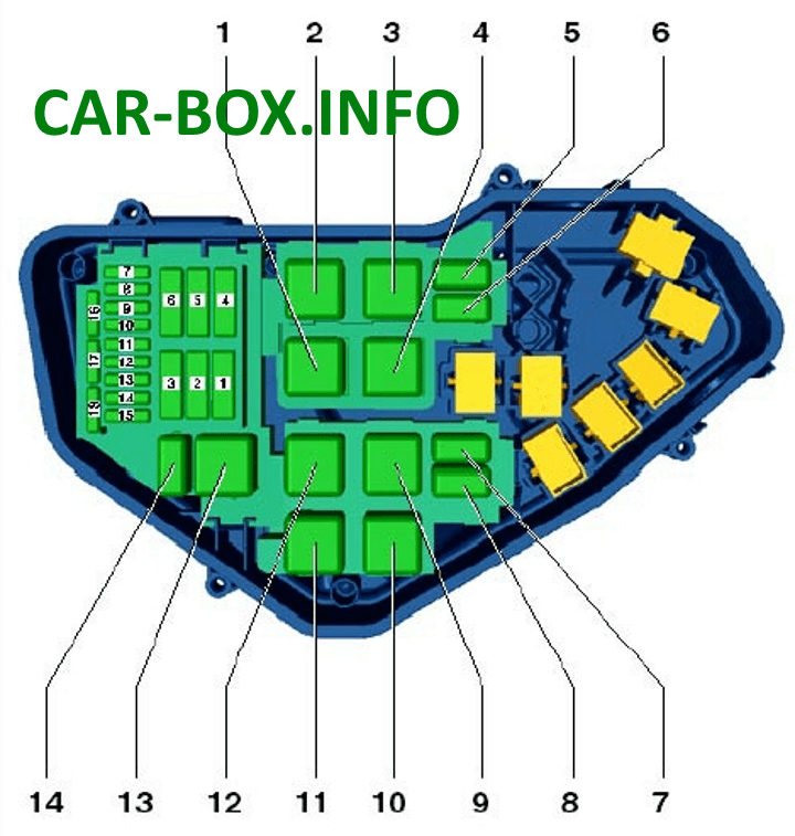
On the right side
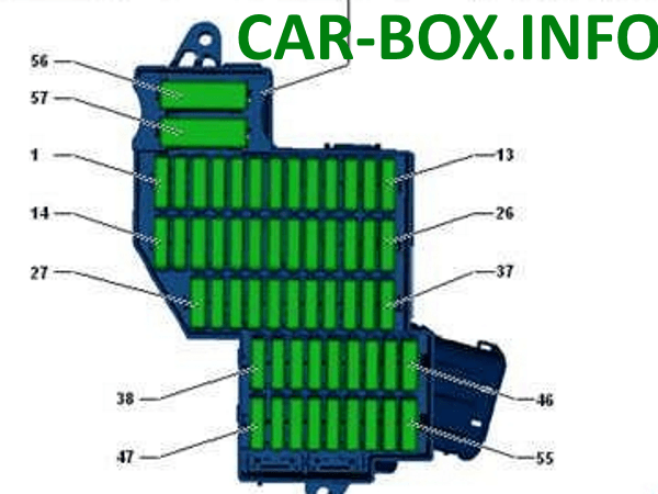
Located on the right side of the dashboard.
| Diagram | |
|---|---|
|
|
| № | Amps / Description |
| 1 | Not used |
| 2 | 15A Control unit for ride height control |
| 3 | 10A Interwheel differential lock control unit |
| 4 | 30A Interwheel differential lock control unit |
| 5 | 15 / 25A Trailer recognition control unit |
| 6 | 15A Trailer recognition control unit |
| 7 | 15 / 25A Trailer recognition control unit |
| 8 | 15 / 25A Trailer recognition control unit |
| 9 | 30A Rear right door control unit |
| 10 | Not used |
| 11 | 30A Front passenger door control unit |
| 12 | Not used |
| 13 | 15A Trailer recognition control unit |
| 14 | 10A Airbag control unit, control unit for seat occupied recognition |
| 15 | 10A Transfer case control unit |
| 16 | 5A Electromechanical parking brake control unit, Ride height control panel, washer jets heating resistor, ASR and ESP off button, ABS control unit, Downhill assist button, Electromechanical parking brake button, AUTO HOLD button, Voltage stabilizer |
| 17 | 15A Right headlight |
| 18 | 30A Seat belt pretensioner igniter 2, front passenger side |
| 19 | 5A Tiptronic switch, Multifunction switch, Automatic transmission control unit |
| 20 | 25A Front passenger seat adjustment control unit, driver and passenger seat control unit |
| 21 | 25A Rear seat heating control unit, Rear air conditioning control and display panel |
| 22 | Not used |
| 23 | 25A Tailgate control unit |
| 24 | 10A Climatronic control unit, rear air conditioning control and display panel |
| 25 | 5A Outdoor camera control unit, Rear view camera control unit |
| 26 | 30A Rear window defogger relay |
| 27 | 5A Device for receiving radio signal of an additional liquid heater |
| 28 | 5 / 20A Gearbox hydraulic pump relay, Transfer case control unit, Automatic transmission control unit (Before November 2012) |
| 29 | 30A ABS control unit |
| 30 | 5A Tiptronic switch |
| 31 | 20 / 30A Central control unit for comfort system |
| 32 | 30A Rear intake fan |
| 33 | 30A Central control unit for comfort system |
| 34 | Not used |
| 35 | 5A Vehicle tracking system control unit |
| 36 | 30A Central control unit for comfort system |
| 37 | 20A Automatic gearbox control unit, Gearbox hydraulic pump relay |
| 38 | 15A Cigarette lighter, 12V socket 2, Rear seat heating control unit (Before August 2014) |
| 39 | 15A Additional 12 V sockets |
| 40 | 20 / 30A Inverter with socket, 12 V - 230 V |
| 41 | 10A Connector 2 for connecting external audio devices |
| 42 | 5A Trailer recognition control unit |
| 43 | 10A Interwheel differential lock control unit |
| 44 | 5A Air pollution sensor |
| 45 | 30A Voltage stabilizer |
| 46 | 30A Voltage stabilizer |
| 47 | 10A Electronic information system control unit |
| 48 | 30A Digital audio system control unit |
| 49 | Not used |
| 50 | 5A TV tuner, Mobile phone control electronics control unit |
| 51 | 20A Head unit |
| 52 | 5A Control unit in dash panel insert -J285- |
| 53 | 5A DVD changer |
| 54 | 5A Interface for external multimedia devices -R215- |
| 55 | Not used |
| 56 | 40A ABS control unit |
| 57 | 40A Electromechanical parking brake control unit, Transfer case control unit |
In the 2nd generation Volkswagen Tuareg, fuse number 38 at 15A is responsible for the front cigarette lighter, and for additional number 39.
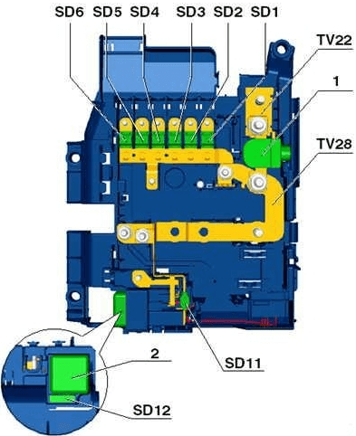
Under the driver's seat
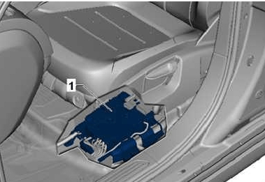
Location.
| Diagram | |
|---|---|
|
|
| № | Amps / Description |
| 1 | 100A Fuse box |
| 2 | 50A Control unit for ride height control |
| 3 | 100A Fuse box |
| 4 | 80A Fuse box |
| 5 | 40A Fuse box |
| 6 | 50A Socket relay, Fuse box |
| 7 | 60A Fuse Box, Rear Supply Fan |
| 8 | 60A Wire connector, Terminal 30 power supply relay |
| 9 | 125A Fuse box |
| 10 | 60 / 150А Heating element for additional air heater, GB hydraulic pump relay |
| 11 | 40A Power supply relay terminal 15 |
| 12 | 5A Diagnostics |
Under-dash relay boxes
The following blocks are located in the area of the steering rack.
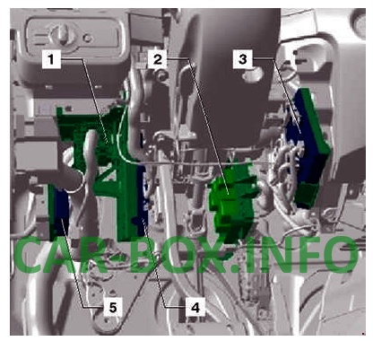
Block assignment:
- Fuse and relay box 1
- Fuse and relay box 2
- Onboard supply control unit
- Convenience system central control unit
- Parking aid control unit
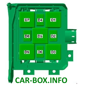
Box 1

- E1 - Heated windscreen relay, left (643)
- E2 - Heated front windscreen relay (643), Coolant low warning switch control unit (422)
- E3 - Socket relay (100)
- E4 - Gearbox hydraulic pump relay (644)
- E5 - Residual heat battery relay (404), Coolant level relay (646)
- E6 - Fan release relay (449)
Box 2
- Ride height control compressor relay (373)
- Coolant Level Switch (404), Residual Heat Accumulator Relay (646)
- Heated windscreen relay, left (645)
- Horn relay (395)
- Gearbox hydraulic pump relay - (100), Socket relay (644)
- Gearbox hydraulic pump relay (404), gearbox hydraulic pump relay (646)
- Heated rear window relay (643)
- Fan release relay (646)
- Coolant low level warning switch control unit (422), Right windscreen heating relay (645)
In the engine compartment

Fuse box is located in the connection box, in the plenum chamber on the left.
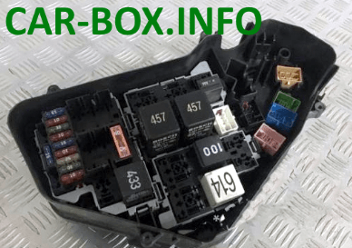
Photo - example
| Diagram | |
|---|---|
|
|
| № | Amps / Description |
| 1 | 40A Starter relay, Starter |
| 2 | Not used |
| 3 | 40A Secondary air pump relay |
| 4 | 30A Vacuum pump relay |
| 5 | Not used |
| 6 | Not used |
| 7 | 15A Fuel pressure regulator, Fuel metering valve, Ignition coil |
| 8 | 10A Exhaust gas recirculation radiator pump |
| 9 | 30A Engine control unit |
| 10 | 10A Radiator fan control unit, Glow plug control unit, Additional coolant pump relay, Brake light switch, EGR cooler changeover valve, Throttle valve, Cylinder head coolant valve, Oil pressure regulating valve, Electronic coolant control thermostat engine, throttle body |
| 11 | 5A Oil level and temperature sensor |
| 12 | 10A Relay for auxiliary coolant pump, Relay for residual heat battery, Coolant circulation pump |
| 13 | 25A Fuel pump control unit |
| 14 | 15 / 30A Reducing agent pump, Reducing agent level estimation module, Engine control unit 2 |
| 15 | 10 / 30A Terminal 30 voltage supply relay, Engine control unit |
| 16 | 30A Reductant heating system control unit |
| 17 | 15A Lambda probe heating element |
| 18 | 10A Lambda probe heating element |
| № | Relay |
| 1 | Glow plug control unit (457) |
| 2 | Engine electronics supply relay (645) |
| 3 | Secondary air pump relay (100) |
| 4 | Main relay (614) |
| 5 | Reserve |
| 6 | Additional coolant pump relay (404) |
| 7 | Reserve |
| 8 | Reserve |
| 9 | Starter relay (100) |
| 10 | Brake servo relay (100) |
| 11 | Reserve |
| 12 | Reserve |
| 13 | Starter relay 2 (433) |
| 14 | Reserve |
