Volkswagen Touran is a compact van with five or seven seats. The 1st generation was produced with gasoline and diesel engines in 2003, 2004, 2005, 2006, 2007, 2008, 2009, 2010, 2011, 2012, 2013, 2014 and 2015. During this period, the car was restyled 2 times. Since 2016, the 2nd generation has been in production. In our material you will find a description of the 1st generation Volkswagen Touran fuse blocks and relays with photo examples and block diagrams. Separately highlight the cigarette lighter fuse.

Volkswagen Touran 1st generation has been updated 2 times, respectively, the value of fuses and relays in the blocks may differ from the one presented and depends on the year of manufacture and the level of vehicle equipment.
In the passenger compartment
Fuse box
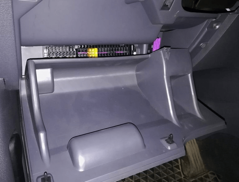
All main units are located under the dashboard, on the driver's side, behind the glove compartment.

The cover can be removed for easy access.

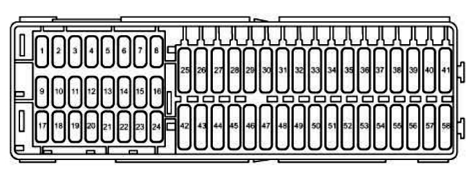
General structure
| Diagram | |
|---|---|
|
|
| № | Amps / Description |
| 1 | 5 / 10A Electrochromic interior rearview mirror, Onboard supply control unit |
| 2 | 5 / 10A Trailer connector, Data bus diagnostic interface, Fuel pump relay, Engine control unit, Power supply relay cl. thirty |
| 3 | 5A Relay for headlamp cleaning, Control unit for headlight range control, Power steering control unit, Trailer detection control unit, Control unit for adaptive lighting and headlight range control, Trailer detection control unit , Brake light switch, ESP and ASR warning lamp 2, Adjustment button rear left seat cushion angle, ASR switch, Tire pressure indicator button, DSG gearbox mechatronic unit, Automatic gearbox control unit, ABS control unit, ASR and ESP off button |
| 4 | 10A Fuel pump control unit, garage door opener control unit |
| 5 | 5A Heated front seats, Air flow meter, Heating resistor for crankcase ventilation, Warning buzzer for training car, Control unit for electronics control of mobile phone |
| 6 | 5A Airbag control unit, Front passenger airbag deactivation warning lamp |
| 7 | 5A Heated front seats heater air conditioner |
| 8 | 5A Heated windshield washer nozzles |
| 9 | 5A Airbag 10A Onboard supply control unit, Adaptive lighting and headlight range control unit |
| 10 | 5A Telephone, data bus diagnostic interface |
| 11 | 10A Power steering, Park assist control unit |
| 12 | 5 / 10A Automatic transmission, Fuel pump control unit, Left headlight range control actuator, Headlight range control unit, Trailer recognition control unit |
| 13 | 10A Headlight range control |
| 14 | 5 / 10A Anti-lock braking system (ABS), Engine control unit 2, Crankcase ventilation heating resistor, Fuel pump control unit |
| 15 | 5A Diagnostic connector (DLC), reversing lights, Airbag control unit, Anti -theft alarm remote control, taxi, Mirror with taximeter, Tiptronic switch |
| 16 | 5A Data bus connector, Instrument cluster control unit, Fresh air blower switch, Heater and operating mode selection switch, High pressure sensor, Driver's seat heating control unit, Quick heating button, Parking aid button |
| 17 | 7,5А Special cars |
| 18 | 5A Emergency Data Logger, Taxi Anti-Theft Remote Control Unit |
| 19 | 5A Luggage compartment light, left, Taximeter |
| 20 | 10A Parking system control unit, Automatic gearbox control unit, ABS control unit |
| 21 | 5 / 10A Radio signal receiver for auxiliary coolant heater, Multifunction switch, Onboard supply control unit, Automatic gearbox control unit, Selector lever position sensor control unit, Multifunction switch |
| 22 | 7.5A Additional heater, Multimedia system control unit |
| 23 | 10A Stop lights, Voltage monitoring relay |
| 24 | 10A Auxiliary heater, diagnostic connector (DLC), heating air conditioning, light switch |
| 25 | 20A Brake vacuum pump, Automatic gearbox control unit |
| 26 | 10A Engine management (Injectors, ignition coils) |
| 27 | 20A Automatic gearbox control unit |
| 28 | 5A Light switch, Rain and light sensor, Climatronic control unit |
| 29 | 15A Rear window wiper motor, Windscreen and rear window washer pump |
| 30 | 20A Headlamp socket, Rear cigarette lighter, Blocking diode |
| 31 | 15A Additional heater |
| 32 | 15A Windshield Washer |
| 33 | 10A Service vehicles 40A Heater and operating mode selection switch, Fresh air blower relay, Air conditioning control unit |
| 34 | |
| 35 | 10A / 40A Heater air conditioner |
| 36 | 10A Service vehicles |
| 37 | - |
| 38 | - |
| 39 | - |
| 40 | 20A Trailer electrical connector |
| 41 | 20A Trailer electrical connector or TSU socket (cigarette lighter) |
| 42 | 15A Accessory Power Connector (Cigarette Lighter) |
| 43 | 15A Fuel pump control unit |
| 44 | 5A Anti-theft system, 40A Supply fan control unit |
| 45 | 20A Audio system, Sliding sunroof control unit |
| 46 | 5A Multifunction control unit 1 |
| 47 | (25A) Volkswagen Touran cigarette lighter fuse or front seat control unit |
| 48 | 20A Headlight washer system, Front seat control unit |
| 49 | 10A Door control unit (driver), door control unit (passenger) |
| 50 | 30A Heated front seats, Convenience system central control unit |
| 51 | 20A Hatch |
| 52 | 25A Multifunctional control unit 1, auxiliary heater |
| 53 | 25A Multifunction control module 2, Headlamp cleaning relay |
| 54 | 5A automatic transmission |
| 55 | 5A Service vehicles |
| 56 | 15A / 40A Heater air conditioner |
| 57 | 30A Door control unit (driver), door control unit (passenger) |
| 58 | 30A Door ECM (rear left), door ECM (rear right) |
| Fuse numbers 30, 42 and 47 are responsible for the cigarette lighter. | |
Relay box #1
Located on the onboard supply unit.
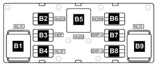
Designation
- B1 - J681 - terminal 15 power supply relay 2 (460)
- B2 - J99 - outside mirror heating relay (449)
- ВЗ - not used
- B4 J689 Terminal 30 power supply relay 2 (449)
- B5 - J9 - rear window heating relay (53)
- B6 - J 4 - two-tone horn relay (449)
- B6 - J 413 - horn relay (449)
- B7 - J729 - relay 1 double washer pump (404)
- B8 - J 730 - relay 2 double washer pump (404)
- B9 - J 59 - relay unloading contact X (460)
J4 and J413 are mini-relays and are installed (depending on the equipment) in one socket of the relay block.
Relay box #2
Located above the onboard supply control unit.
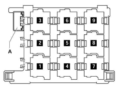
Appointment
1. J496 - Relay for additional coolant pump (449)
2. J39 - Relay for headlight cleaning system (53)
3. 1) J17 Fuel pump relay (449) 2) J643 Fuel pressure relay (449)
4. J13 - supply fan relay (404)
5. J3ЗЗ - fuel pump shutdown relay (404)
6. not used
7. J485 - Relay for auxiliary heater operation (449)
8. J682 - Terminal 50 power supply relay (433), from May 2006 (53)
9. not used
A - Thermal fuse 1 for driver's seat adjustment - 30A. J17 and J643 are mini-relays and are installed (depending on equipment) in one slot of the relay block.
In the engine compartment
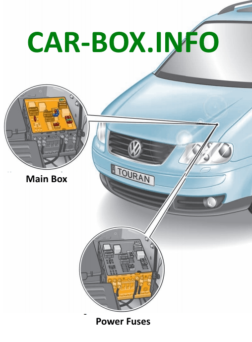
Location
Main fuse box
This communication box is located on the left side of the engine compartment, next to the battery.
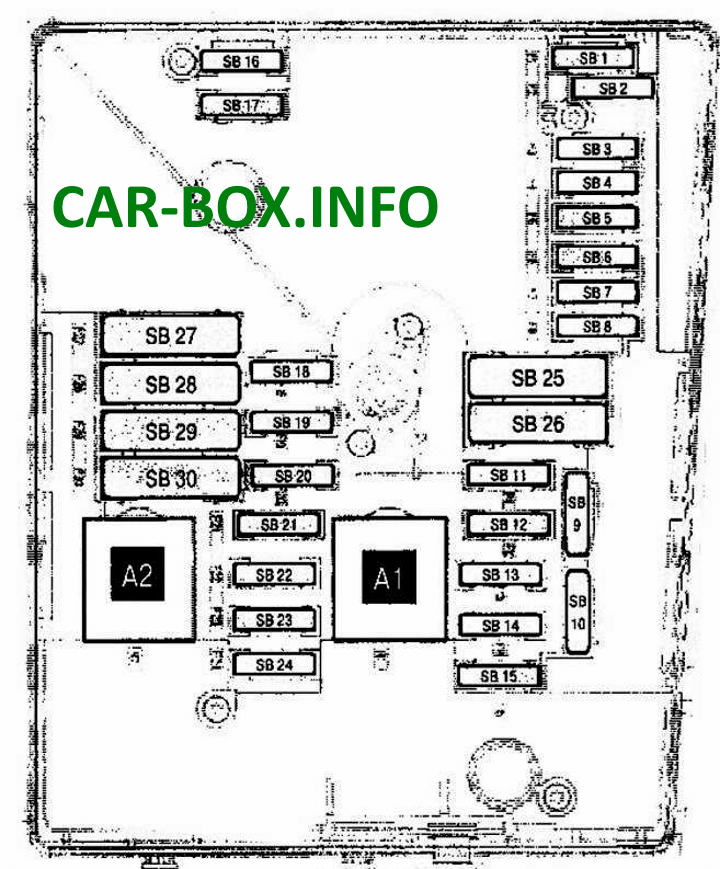
Type 1
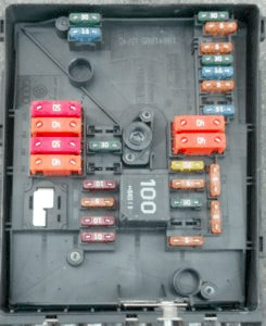
General view.
| Diagram | |
|---|---|
|
|
| № | (Amps) Description |
| A1 | (100/458) Ignition main circuit relay |
| A2 | (100) Exhaust air pump relay (BSX) |
| 1 | (20A / 25A / 30A) Windshield wiper motor 2 (dual wiper motor system) |
| 2 | (5A) Steering column control module |
| 3 | (5A) Multifunction control module 1 |
| 4 | (30A) Anti lock brake system (ABS) |
| 5 | (15A) Transmission control system (automatic transmission) (manual transmission (DSG) |
| 6 | (5A) Instrument cluster control module |
| 7 | - |
| 8 | (15A) Audio system, navigation system |
| 9 | (5A) Telephone |
| 10 | (5A / 10A) Engine management |
| 11 | (20A) Auxiliary heater |
| 12 | (5A) Diagnostic unit |
| 13 | (25A / 30A) Engine management |
| 14 | (20A) Engine management |
| 15 | (5A / 15A) Engine management |
| 16 | (30A) Anti lock brake system (ABS) |
| 17 | (15A) Horn, multifunction control module 1 |
| 18 | (30A) Audio system (some models), special vehicle |
| 19 | (30A) Windshield wiper motor 1 |
| 20 | (40A) Glow plug control module |
| 21 | (10A / 15A) Engine management |
| 22 | (5A) Brake light switch (brake pedal position sensor), clutch pedal position sensor |
| 23 | (5A / 10A / 15A) Engine management |
| 24 | (10A) Cooling fan motor control module, coolant pump relay (some models), thermostat, engine management |
| 25 | (40A) Multi-function control module 1 |
| 26 | (40A) Multi-function control module 1 |
| 27 | (40A / 50A) Glow plug control module, exhaust air pump motor |
| 28 | (40A) Multifunction control module 1, multifunction control module 2 |
| 29 | (50A) Coolant pump relay (some models) |
| 30 | (40A) Instrument cluster 1 fuse / relay box (F7 / F8 / F28-F35), auxiliary ignition circuit relay |
Type 2

General view.
| Diagram | |
|---|---|

|
|
| № | Amps / Description |
| A1 | Relay 2 main ignition circuits |
| A2 | Starter relay |
| A3 | Fuel pump relay - 1.6 (BGU) |
| A4 | Relay 1 of the main ignition circuits |
| 1 | 30A Anti-lock braking system (ABS) |
| 2 | 30A Anti-lock braking system (ABS) |
| 3 | 25A Windshield wiper |
| 4 | 5A Multifunction control unit 1 |
| 5 | 20A Multifunction control unit 1, Signal |
| 6 | 15A / 20A Engine management system, Ignition coil - petrol |
| 7 | 5A Engine Management, Clutch Pedal Position Sensor |
| 8 | 10A Cooling blower motor, Exhaust gas recirculation valve |
| 9 | 10A Engine Management, Fuel Pump Relay, Glow Plug Control Unit |
| 10 | 5A / 10A Engine Management, Secondary Air Pump Relay, Lambda Sensor |
| 11 | 25A / 30A Engine management |
| 12 | 15/25 / 30A Engine management, Motronic control unit, Injection system control unit |
| 13 | 15A automatic transmission |
| 14 | |
| 15 | 40A Starter |
| 16 | 15A Steering column control module |
| 17 | 10A Instrument Cluster |
| 18 | 30A Audio system |
| 19 | 15A Audio system |
| 20 | 10A Phone |
| 21 | |
| 22 | |
| 23 | |
| 24 | 10A Data bus connector |
| 25 | |
| 26 | 10A Engine management system - except 1.6 (BGU), Motronic control unit |
| 27 | 10A Crankcase ventilation heater |
| 28 | 20A automatic transmission |
| 29 | 10 / 20A Engine Management - 1.6FSi (BAG) / 2.0FSi (AXW), Ignition Coils |
| 30 | 20A Additional heater |
| 31 | 25A Windshield wiper |
| 32 | 10A Engine management, Cylinder injectors |
| 33 | 15A Booster fuel pump |
| 34 | - |
| 35 | - |
| 36 | - |
| 37 | - |
| 38 | 10A Headlight range control |
| 39 | 5A Engine oil temperature sensor, instrument cluster |
| 40 | 20A Dashboard relay fuse box 1 |
| 41 | - |
| 42 | 5A Engine Management, Air Mass Meter, Engine Electronic Components Power Relay |
| 43 | 20A brake booster vacuum pump |
| 44 | - |
| 45 | 15A Heated oxygen sensor, Lambda probe |
| 46 | - |
| 47 | 40A Multifunction control module 1 |
| 48 | 40A Multifunction control module 1 |
| 49 | 50A Relay 1 main ignition circuits |
| 50 | - |
| 51 | 40A Glow plug control unit |
| 52 | 50A Multifunction control unit (Onboard supply control unit) |
| 53 | 50A Door control units, instrument panel fuse / relay box |
| 54 | 50A Radiator fan control unit |
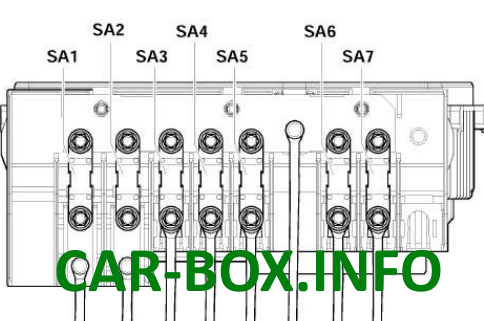
Power fuse panel
It consists of high power fusible rates.
| Diagram | |
|---|---|
|
|
| SA1 | (150A / 200A) Generator |
| SA2 | (80A) Power steering |
| SA3 | (80A) Cooling fan motor |
| SA4 | (80A) Service vehicles |
| SA5 | (100A) (for vehicles manufactured after October 2005) - additional heater |
| SA6 | (80A / 100A) Dashboard fuse / relay box 1 (F20-F24 / F42-F56) 40A Low heating power relay |
| SA7 | (50A) Dashboard fuse / relay box 1 (F39 / F41) (for vehicles manufactured before April 2006) - trailer electrical |
Additionally, on the bottom of this unit, in a model with a diesel engine, a relay unit can be installed to control and protect the glow plugs.
