Alfa Romeo 145 / 146 - three- and five-door hatchbacks of small family class, produced by the company from 1994 to 2001. The models are built on the Fiat Type Two (Tipo Due) platform together with Fiat Bravo/Brava and were produced simultaneously with them as more luxurious variants. In this article, we will take a detailed look at the fuse box diagrams for the Alfa Romeo 145 / 146 (930 series) 1994, 1995, 1996, 1997, 1998, 1999, 2000, 2001 years of manufacture.
Here you will find the locations and photos of distribution boxes. The fuses responsible for the “Cigarette lighter” and “Fuel Pump” are highlighted in bold.
In the engine compartment
There are two distribution boxes here that are responsible for protecting the electrical circuits.
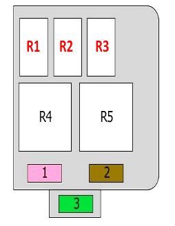
Main fuse box
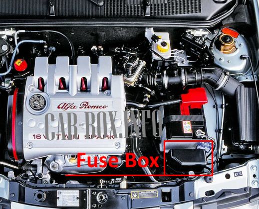
It is located near the battery. The protective cover must be removed for access.
| Diagram (type 1) | ||
|---|---|---|
|
||
| No. | Description | A |
| 1 | Air conditioner condenser fan relay 1 | 30 |
| 2 | Air conditioning compressor | 7.5 |
| 3 | Air conditioner | 30 |
| R1 | Air conditioner fan motor | |
| R2 | Air conditioner | |
| R3 | Air conditioner compressor solenoid clutch relay | |
| R4 | Air conditioner condenser fan relay 2 | |
| R5 | Air conditioner condenser fan timer relay | |
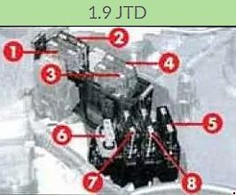
| Diagram (Type 2) | ||
|---|---|---|
|
||
|
||
| 1 | Vehicle electrical equipment operating from the ignition switch | 30 |
| 2 | Cooling fan | 40 |
| 3 | Vehicle electrical equipment | 60 |
| 4 | Vehicle electrical equipment | 60 |
| 5 | ABS | 60 |
| 6 | Ignition system, injector (gasoline engines) | 30 |
| 7 | Additional heater (1.9 JTD) | 70 |
| 8 | Glow plugs, resistance to fuel filter (1.9 JTD) | 60 |
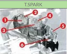
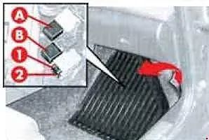
Additional fuse box
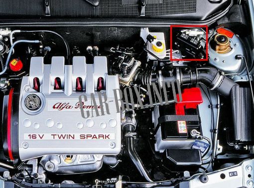
It is located near the windshield. Its design depends on the engine type.
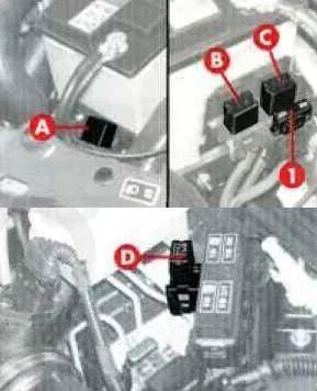
| T.SPARK | ||

|
||
| 1 | Injector | 15A |
| 2 | Injector | 15A |
| A | Main relay | |
| B | Fuel pump relay | |
| C | Climate control compressor relay | |
| D | Cooling fan relay (2nd speed) | |
| 1.9 JTD | ||
|
||
| 1 | Cooling fan | 40A |
| A | Cooling Fan Relay (2nd Speed; Vehicles with Heater) | |
| B | Cooling fan relay (1st speed) | |
| C | Cooling fan relay (2nd speed) | |
| D | Climate control compressor relay | |
In the passenger compartment
There are three distribution boxes here, which are responsible for protecting the vehicle's electrical circuits.
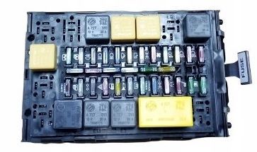
Main fuse box
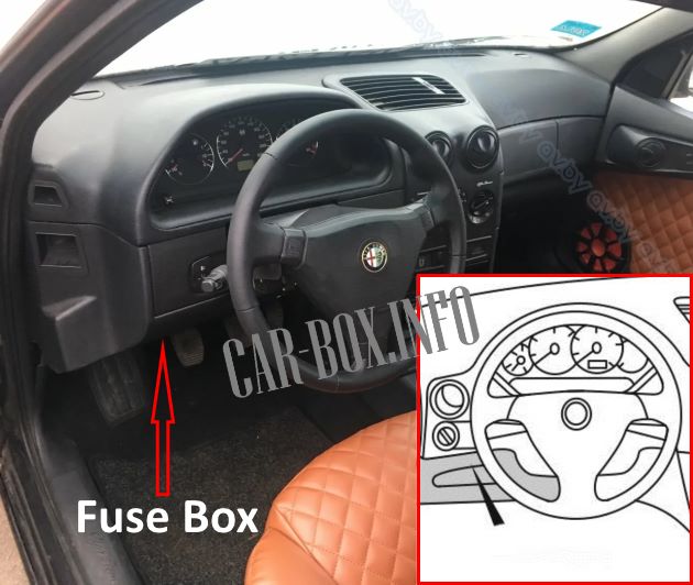
Located to the left of the steering column under the instrument panel. To access it, press the "FUSE" button.
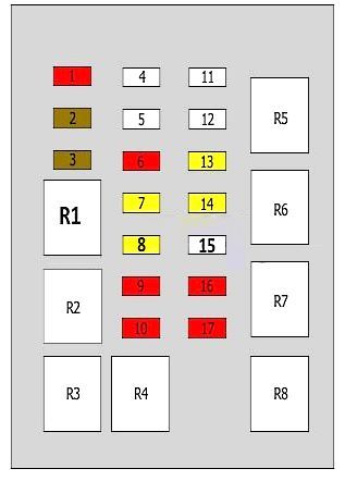
Type 1
Diagram.
|
||
| No. | Description | A |
| 1 | Emergency alarm | 10 |
| 2 | Indicators, air conditioner compressor control unit, cooling fan motor timer relay, sunroof control unit | 7.5 |
| 3 | Rear fog lights | 7.5 |
| 4 | Instrument cluster, windshield washer, headlight washers, reversing lights, SRS (airbag), power mirrors, auxiliary alarm unit | 15 |
| 5 | Dipped beam - left headlight | 10 |
| 6 | Dipped beam - right headlight | 10 |
| 7 | windshield wiper | 20 |
| 8 | heater fan | 20 |
| 9 | High beam - right headlight | 10 |
| 10 | High Beam - Left Headlight | 10 |
| 11 | Clock, interior lighting, instrument panel, central locking system | 20 |
| 12 | Cooling fan motor | 25 |
| 13 | Horn, Alfa Romeo 145 / 146 cigarette lighter fuse, brake lights, audio system | 20 |
| 14 | windshield wiper | 20 |
| 15 | Rear window heater | 25 |
| 16 | Instrument panel illumination, switch illumination, tail lights-left, license plate illumination-right, front lights-right, tail light switch buzzer | 10 |
| 17 | Rear position lamp - right, license plate lamp - left, front position lamp - left. | 10 |
| R1 | Dipped beam headlights relay | |
| R2 | Start inhibit switch relay | |
| R3 | Main Beam Relay | |
| R4 | Windshield Wiper Intermittent Relay | |
| R5 | Horn relay | |
| R6 | Rear window heater relay | |
| R7 | Rear fog light relay | |
| R8 | Position Lamp Relay | |
Type 2
General view.
| Diagram | ||
|---|---|---|
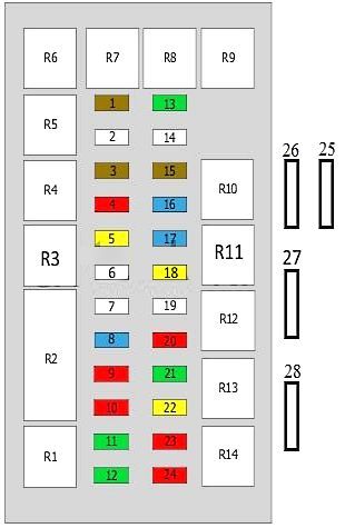
Diagram. |
||
| No. | Purpose | A |
| 1 | Headlight dipped beam / main beam | 7.5 |
| 2 | Reserve | |
| 3 | Turn indicators, power windows - front, air conditioner compressor, cooling fan motor timer relay, tailgate opener actuator | 7.5 |
| 4 | Emergency alarm system, anti-theft system | 10 |
| 5 | central locking system | 20 |
| 6 | Horn, cigarette lighter, audio, brake lights | 25 |
| 7 | Rear window heater, rear view mirror heater | 30 |
| 8 | Instrument cluster, windshield washer, headlight washers, reversing lights, SRS (airbag), power door mirrors, auxiliary alarm unit, immobilizer | 15 |
| 9 | Rear position lamp - right, license plate illumination lamp - left, front position lamp - left, headlight corrector | 10 |
| 10 | Clock, interior lamps, instrument cluster, central locking signal control unit | 10 |
| 11 | seat heater | 30 |
| 12 | Cooling fan motor (except 2.016V) | 30 |
| 13 | sunroof | 30 |
| 14 | Power window elevator, left front | 25 |
| 15 | Rear fog lights | |
| 16 | Main beam - right headlight | 15 |
| 17 | Main Beam - Left Headlight | 15 |
| 18 | windshield wiper | 20 |
| 19 | Rear window heater, seat heater, cooling fan (2.0 16V) | 25 |
| 20 | Instrument cluster illumination, rear position lamp - left, license plate illumination lamp - right, front position lamp - right, warning buzzer for lights left on | 10 |
| 21 | Heater fan motor | 20 |
| 22 | Fog lights | 20 |
| 23 | Dipped beam - right headlight | 10 |
| 24 | Dipped beam - left headlight | 10 |
| 25 | Power windows | 25/30 |
| 26 | ABS system | 10 |
| 27 | Door mirror heaters | 7.5 |
| 28 | headlight washer | 20 |
| R6 | Central locking system signal control unit, interrupter | |
| R5 | Windshield wiper intermittent operation relay | |
| R4 | Front/rear position relay | |
| R3 | Horn relay | |
| R2 | Central lock control unit | |
| R1 | Rear defroster relay | |
| R7 | — | |
| R8 | Cooling Fan Motor Relay | |
| R9 | sunroof relay | |
| R10 | Rear fog light relay | |
| R11 | High Beam Relay | |
| R12 | Start prohibition switch relay | |
| R13 | Fog lamp relay | |
| R14 | Dipped beam relay | |
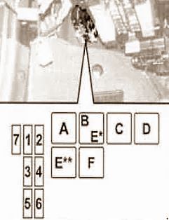
Additional block #1
Located next to the main unit.
| Diagram | ||
|---|---|---|
|
||
| No. | Description | A |
| 1 | Air conditioning compressor | 10 |
| 2 | headlamp cleaner | 20 |
| 3 | Power windows, central locking system | 30 |
| 4 | Safety Airbags, instrument cluster | 10 |
| 5 | Heated mirrors | 7.5 |
| 6 | Anti-theft system | 20 |
| 7 | Alfa Romeo Code (T.SPARK) | 7.5 |
| A | Direction indicator relay | - |
| B | Fuel oil warming control relay (1.9 JTD) | - |
| C | Headlight cleaner relay | - |
| D | Passenger Power Window Relay | - |
| E | Mirror heating relay | - |
| F | Luggage door opener relay | - |
Additional block #2
1.9 JTD engines only. Located in the front passenger floor recess.
| Diagram | ||
|---|---|---|
|
||
| No. | Description | A |
| 1 | Alfa Romeo Code | 7.5 |
| 2 | Injector | 7.5 |
| A | Fuel pump relay | |
| B | Main relay | |
All electrical equipment
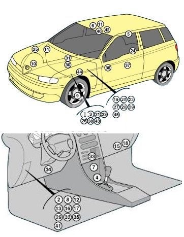
General layout of electronic components in the vehicle.
1. Air conditioning condenser fan motor relay (2.0 16V);
2. Air conditioner condenser fan motor relay;
3. Electronic air conditioner control module;
4. SRS electronic control module;
5. Anti-theft system control module;
6. Volume change sensor (anti-theft system);
7. Start prohibition switch relay (anti-theft system) (yellow);
8. Trunk/rear door lock actuator relay (yellow);
10. Brake pad wear sensor (right front);
11. Central locking system signal control module;
12. Daytime running light relay (green);
13. Daytime running light relay;
14. Diagnostic connector (alternate);
15. Diagnostic connector;
16. Power window relay;
17. Power window control module;
18. Electronic engine control module;
19. Electronic engine control module fuse - 7.5A (1.6/1.7);
20. Relay 1 of the electronic engine control module (1.6/1.7i);
21. Relay 1 of the electronic engine control module (2.0 16V);
22. Relay 2 of the electronic engine control module (1.6/1.7i);
23. Relay 2 of the electronic engine control module (2.0 16V);
24. Fuel pump;
25. Fuel pump relay (1.3/1.6/1.7i);
26. Fuel pump relay (2,0 16V);
27. Fuel pump relay fuse - 10A(1,6/1,7i);
28. Fuel pump relay fuse - 20A (1,3i);
29. Interior fuse box;
30. Fuse/relay box, engine compartment 1 (with air conditioning);
31. Fuse box/relay, engine compartment 2 (2.0 16V);
32. Headlamp washer delay relay (black);
33. Heater fan motor relay;
34. Electronic immobilizer control module;
35. Direction indicator relay (gray);
36. Fuel cut-off inertia switch;
37. Cabin lamp switch-off delay relay;
38. Oxygen sensor circuit fuse (2.0 16V);
39. Oxygen sensor circuit fuse (except 2.0 16V);
40. Power sunroof control module;
41. Sunroof fuse (20A);
42. Sunroof motor control module;
43. Intake manifold geometry change relay (2.0 16V);
44. Vehicle speed sensor;
45. Air flow sensor relay (VAF).
