The Alfa Romeo MiTo is a luxury three-door supermini from the Italian automobile company, officially introduced in June 2008 in Milan. It has gone through two restyling: in 2013 and 2016. In this article, we will take a detailed look at the fuse box diagrams for the Alfa Romeo MiTo (955 series) 2008, 2009, 2010, 2011, 2012, 2013, 2014, 2015, 2016, 2017, 2018 model years.

Here you will find the locations and photos of distribution boxes. The fuses responsible for the “Cigarette lighter” and “Fuel Pump” are highlighted in bold.
In the trunk
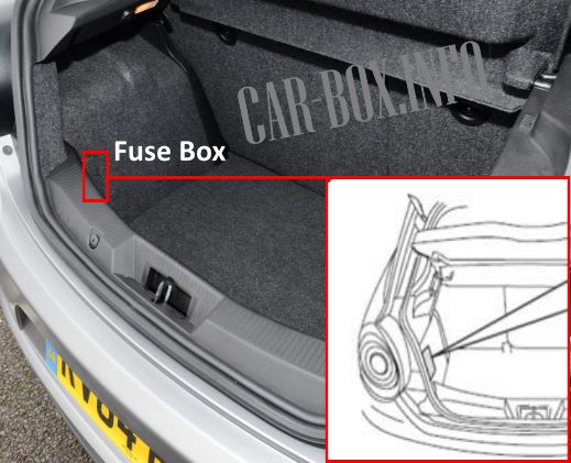
It is located behind the trim on the left side of the luggage compartment.

General view.
| Diagram | ||
|---|---|---|
|
||
| No. | Description | A |
| F1 | Sunroof | 20 |
| F2 | Wiring for fuses | |
| F3 | Power connector for optional equipment | 15 |
| F4 | Audio system | 1 |
| F5 | Audio System - (The Bassbox sybwoofer is located in the spare wheel well) | 10 |
| F6 | Seat heater | 15 |
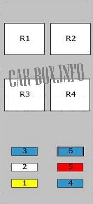
| 1 | Power connector for optional equipment relay | |
| 2 | — | |
| 3 | Seat heater relay | |
| 4 | Seat heater relay | |
In the passenger compartment
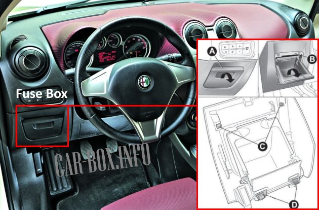
To access the fuses, lower the cover (A) while holding the cover (B) by hand. First remove the inner catches (C) and then the outer catches (D).
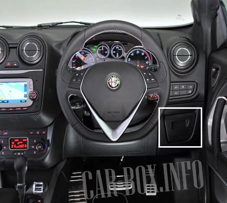
For right-hand drive models, the procedure for accessing the unit is the same.
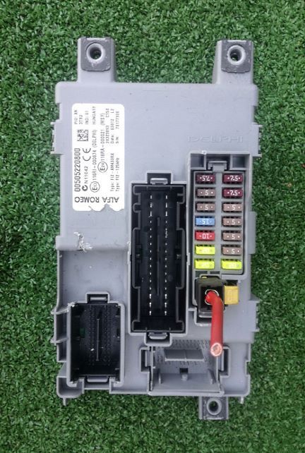
General view of the Alfa Romeo MiTo interior fuse box.
| Diagram | ||
|---|---|---|

|
||
| No. | Description | A |
| F1 | Right headlight | 7.5/15 |
| F2 | Interior lamps | 5 |
| F3 | instrument cluster | 5 |
| F4 | central locking system | 15 |
| F5 | Audio system, Blue&Me system, Air conditioning control unit, Anti-theft alarm siren Volume alarm control unit, EOBD external diagnostic connector, Electronic tire pressure control unit | 10 |
| F6 | Electric windshield and rear window washer pump | 20 |
| F7 | Power windows | 20 |
| F8 | Left headlight | 7.5/15 |
| F9 | SRS system | 7.5 |
| F10 | Reverse | 5 |
| F11 | Third brake light | 5 |
| F12 | Parking sensor control unit, Tire pressure monitoring unit, Rain sensor, automatic headlight sensor on the inside rear view mirrors, electrochromed (convex) inside rear view mirror, radio navigator (backlight), On display LED indicating that the seat belts are fastened on the inside rear view mirror, illuminated controls (on the center panel, on the panel on the driver's side, controls on the steering wheel, Blue&Me controls), Heated switches on the front seats, control unit of the system. | 5 |
| F13 | Fuse box / relay in the engine compartment | 5 |
| F14 | Power windows | 20 |
In the engine compartment
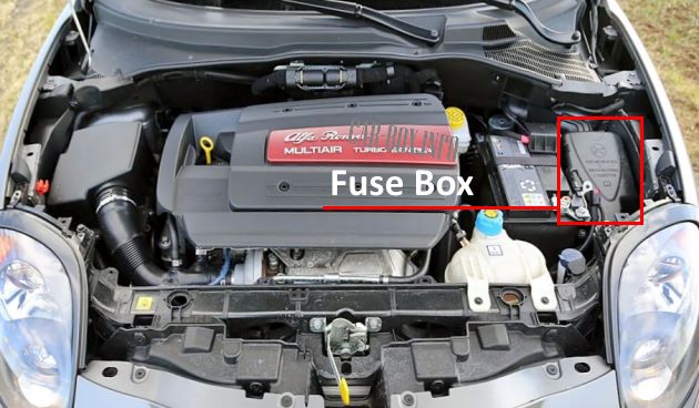
It is located near the battery. To access it, remove the protective cover by unscrewing the two fixing screws.
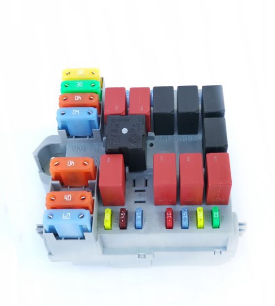
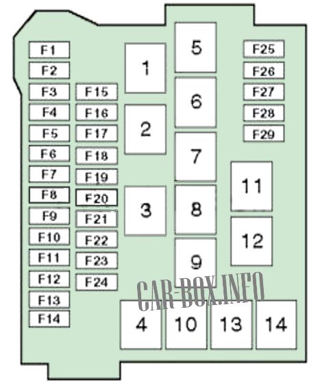
General view.
| Diagram | ||
|---|---|---|
|
||
| No. | Purpose | A |
| F1 | Air conditioner | 7.5 |
| F2 | Headlights | 15 |
| F3 | Horn (beep) | 15 |
| F4 | Additional heater PTC1 | 30 |
| F5 | Control system remote switch coil, engine control unit (version 1.4), engine cooling system deflection coil (300W +300W | 5 |
| F6 | ABS / ESP system | 20 |
| F7 | Fog lights | 15 |
| F8 | Alfa Romeo MiTo fuel pump fuse | 15 |
| F9 | Headlight washers | 20 |
| F10 | Transmission pump | 15 |
| F11 | Rear window heater | 30 |
| F12 | Electronic engine control unit | 5 |
| F13 | Eclectic drive control unit (power + key) / Brake system control unit (power + key) / Deviation sensor on center tunnel | 5 |
| F14 | Heater defrosters for driver's and passenger's side exterior electric mirrors, Heater defrosters for exterior on front mudguards, Windshield heater switch bobbin | 7.5 |
| F15 | Cooling fan motor | 30 / 40 / 50 |
| F16 | Multifunction control box | 70 |
| F17 | ABS/ESP system | 40 |
| F18 | Electric power steering | 70 |
| F19 | Cooling fan motor | 20 / 30 / 40 |
| F20 | Heater fan motor | 40 |
| F21 | Ignition circuits | 20 |
| F22 | 50 | |
| F23 | glow plugs | 60 |
| F24 | Fuse/relay box in luggage compartment | 40 |
| F25 | Engine management | 10 |
| F26 | Engine management | 10 |
| F27 | Engine management | 15 / 20 |
| F28 | Windshield heater | 15 |
| F29 | Alfa Romeo MiTo cigarette lighter fuse; Accessory power connectors | 15 |
| 1 | Fan (high speed) | |
| 2 | Fan (low speed) | |
| 3 | heater fan | |
| 4 | high beam headlights | |
| 5 | Engine management relay | |
| 6 | Windshield heater | |
| 7 | Auxiliary equipment power connector relay | |
| 8 | Fuel pump relay | |
| 9 | Fog lights | |
| 10 | Horn relay | |
| 11 | Start prohibition relay | |
| 12 | Rear window heater | |
| 13 | Air conditioning system | |
| 14 | Headlight washers | |
