
The Alfa Romeo 166 is an executive sedan produced by the Italian automaker from 1998 to 2007. Its design was developed under the direction of the company's chief designer, Walter de Silva. The vehicle received a facelift in 2003. In this article, we provide a detailed overview of the fuse box diagrams for the Alfa Romeo 166 (Type 936), covering all model years from 1998 to 2007.
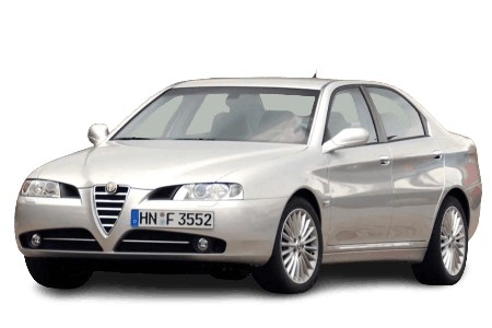
Here, you will find the locations and photographs of the power distribution boxes. The fuses protecting the “Cigarette Lighter” and “Fuel Pump” circuits are highlighted in bold.
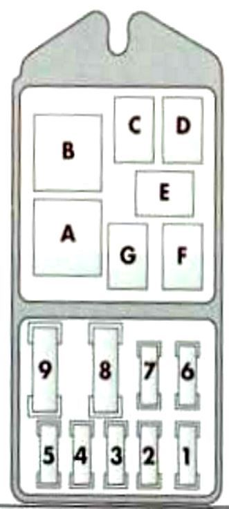
Luggage Compartment
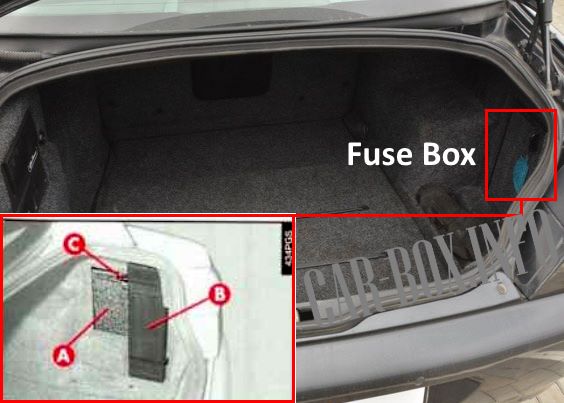
It is located behind the trim panel on the right-hand side.
1998–2002 Model Years
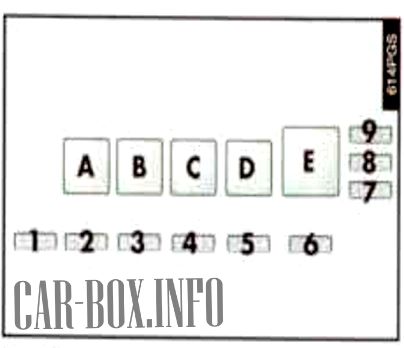
Schematic diagram.
|
||
| No. | Description | A |
| 1 | Heated rear window | 40 |
| 2 | Heated exterior mirrors | 10 |
| 3 | Luggage compartment release actuator | 20 |
| 4 | Fuel filler flap release actuator | 25 |
| 5 | Heated seats | 20 |
| 6 | Trailer towing harness connector | 15 |
| 7 | Power-adjustable seat, right | 30 |
| 8 | Power windows, rear | 25 |
| 9 | Power-adjustable seat, left | 30 |
| No. | Relay Modules | |
| A | Heated rear window relay | |
| B | Luggage compartment release relay | |
| C | Fuel filler flap release relay | |
| D | Heated seats relay | |
| E | Luggage compartment lighting timer | |
2003–2007 Model Years

General overview.
| Diagram | ||
|---|---|---|
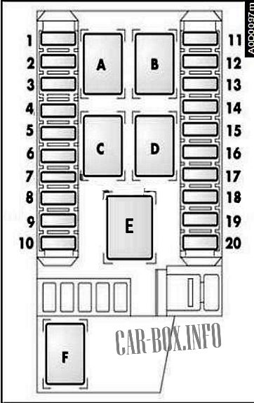
Diagram. |
||
| No. | Description | A |
| 1 | Heated rear window | 30 |
| 2 | Heated exterior mirrors | 7.5 |
| 3 | Body Control Module (BCM) — front right power window | 20 |
| 4 | Spare | |
| 5 | Power-adjustable seat, front right | 30 |
| 6 | Power-adjustable seat, front left | 30 |
| 7 | Heated windshield | 15 |
| 8 | Heated seat, front right | 10 |
| 9 | Heated seat, front left | 10 |
| 10 | Power sunroof | 20 |
| 11 | Spare | |
| 12 | Alarm system control module / Turn signal indicators | 10 |
| 13 | Auxiliary heater (JTD versions) | 10 |
| 14 | BCM — rear left power window | 20 |
| 15 | Remote keyless entry receiver / Parking assist control module / Alarm system control module / Illuminated sun visors / Auto-dimming rearview mirror / Heated seat indicator / Exterior mirror control / Power window lock indicator / Rain sensor | 10 |
| 16 | Rear 12V auxiliary power outlet | 20 |
| 17 | BCM — rear power windows | 20 |
| 18 | BCM — front left power window | 20 |
| 19 | Central locking system | 20 |
| 20 | Audio amplifier | 25 |
Passenger Compartment
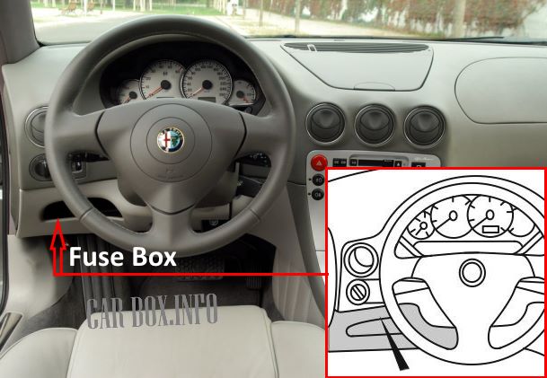
It is located under the dashboard to the left of the steering column, behind a trim panel. To access the fuses, remove the panel by unscrewing the retaining fastener.
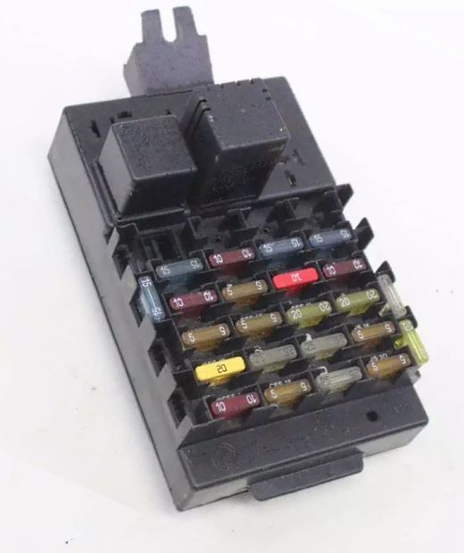
General view of the Alfa Romeo 166 passenger compartment fuse box.
| Diagram | ||
|---|---|---|
|
||
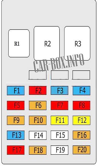
| No. | Description | A |
| F1 | Brake lights, turn signal indicators, instrument cluster | 15 |
| F2 | Supplemental Restraint System (SRS) control module | 10 |
| F3 | Fuel pump fuse (Alfa Romeo 166) | 15 |
| F4 | Audio system | 15 |
| F5 | Glove compartment illumination, power folding mirror control module, cruise control module, alarm system control module, center console multifunction switch (manual transmission only), gear position sensor, A/C compressor magnetic clutch relay, switch illumination, central locking control module, HVAC control panel | 10 |
| F6 | A/C condenser fan motor relay | 5 |
| F7 | Audio/navigation system, HVAC control module, front cigarette lighter | 10 |
| F8 | Turn signal indicators / alarm system, multifunction control module | 10 |
| F9 | Auto-dimming rearview mirror, rain sensor, map lights, heated front seats control module, power window relays, HVAC control module, illuminated vanity mirrors | 5 |
| F10 | Transmission Control Module (TCM) | 5 |
| F11 | Multifunction control module | 20 |
| F12 | Headlight washers | 20 |
| F13 | Exterior lighting, reverse light switch, power sunroof control module | 15 |
| F14 | Windshield wipers/washers | 25 |
| F15 | Power window control module (front) | 25 |
| F16 | Engine Control Module (ECM), immobilizer control module | 5 |
| F17 | Interior lighting / courtesy delay, alarm system control module, alarm siren control module, OBD diagnostic connector, transmission mode switch illumination | 10 |
| F18 | Telematics/phone, instrument cluster, audio/navigation system, HVAC control panel | 5 |
| F19 | Auxiliary power connector, central locking control module | 25 |
| F20 | Immobilizer control module, Engine Control Module (ECM) — gasoline models | 5 |
| R1 | Reverse light relay, heated mirrors and rear window, heated rear window relay | |
| R2 | Turn signal / hazard flasher relay | |
| R3 | Headlight washer timer relay | |
Engine Compartment
2003–2007 Model Years (Facelift)
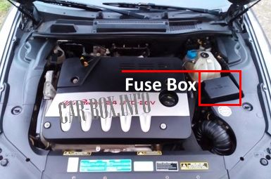
It is located adjacent to the battery, behind a protective plastic cover.
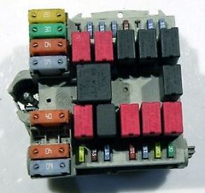
The photograph illustrates an example setup.
| Diagram | ||
|---|---|---|
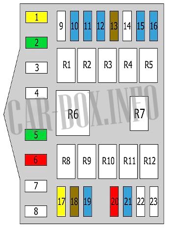
|
||
| No. | Description | A |
| 1 | Ignition switch | 20 |
| 2 | Climate control system | 30 |
| 3 | ABS/ESP control module | 40 |
| 4 | Radiator cooling fan, high speed | 60 |
| 5 | Radiator cooling fan, low speed | 30 |
| 6 | Ignition switch | 10 |
| 7 | ABS/ESP control module | 40 |
| 8 | Glow plugs (Diesel) | 50 |
| 9 | Spare | - |
| 10 | Low beam, right headlight | 15 |
| 11 | Horn | 15 |
| 12 | Headlight leveling system, low beam left headlight | 15 |
| 13 | A/C compressor | 7.5 |
| 14 | Spare | - |
| 15 | Ignition system | 15 |
| 16 | Fog lights | 15 |
| 17 | Auxiliary heater | 20 |
| 18 | Ignition system | 7.5 |
| 19 | Fuel pump (Alfa Romeo 166) | 15 |
| 20 | Ignition system | 10 |
| 21 | Ignition system | 15 |
| 22 | Ignition system | |
| 23 | Diesel fuel heater | |
| No. | Relay Modules | |
| R1 | Low beam relay | |
| R2 | Climate control relay | |
| R3 | Horn relay | |
| R4 | Fog light relay | |
| R5 | Ignition relay | |
| R6 | Radiator cooling fan relay, high speed | |
| R7 | A/C compressor relay | |
| R8 | Radiator cooling fan relay, low speed | |
| R9 | Fuel pump relay | |
| R10 | Main engine relay | |
| R11 | Immobilizer relay | |
| R12 | Diesel fuel heater relay | |
1998–2002 Model Years
Power Distribution Center #1
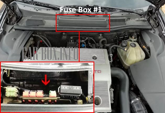
The primary distribution center is located behind a protective cover near the base of the windshield.
| Distribution Center #1 Diagram | ||
|---|---|---|

|
||
| No. | Description | A |
| F1A | Passenger compartment fuse box supply (F4/F8/F10-F12/F15/F17-F20) | 60 |
| F1B | Ignition auxiliary circuits power supply | 30 |
| F2 | A/C refrigerant control valve | 30 |
| F3 | ABS control module | 10 |
| F4 | Automatic transmission control module | 5 |
| F5 | Diesel fuel heater | 15 |
| F6 | Engine Control Module (ECM) (2.0 TS) | 15 |
| F7 | Engine Control Module (ECM) — gasoline models | 15 |
| F8 | Starter motor | 30 |
| F9 | Engine Control Module (ECM) | 30 |
| F10 | Auxiliary heater (Diesel) | 30 |
| F11 | Auxiliary power connector | 25 |
| 1 | HVAC blower motor relay | |
| 2 | Starter relay | |
| 3 | Diesel fuel heater relay | |
| 4 | Engine management main relay | |
| 5 | Fuel pump relay | |
| 6 | Auxiliary heater relay (Diesel, if equipped) | |
Power Distribution Center #2
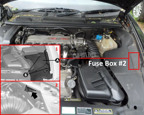
Located behind the trim panel near the left-hand headlight assembly. To gain access, remove cover (A) by turning retaining screws (B).
| Distribution Center #2 Diagram | ||
|---|---|---|
|
||
| No. | Description | A |
| F1 | High beam, right headlight | 10 |
| F2 | High beam, left headlight | 10 |
| F3 | Fog lights | 15 |
| F4 | Horns | 15 |
| F5 | A/C compressor magnetic clutch | 10 |
| F6 | Low beam, left headlight | 15 |
| F7 | Low beam, right headlight | 15 |
| F8 | Radiator cooling fan motor | 50 |
| F9 | Radiator cooling fan motor, low speed | 50 |
| No. | Relay Modules | |
| 1 | Radiator cooling fan relay 1 | |
| 2 | Radiator cooling fan relay 2 | |
| 3 | Low beam relay | |
| 4 | High beam relay | |
| 5 | Horn relay | |
| 6 | A/C compressor relay | |
| 7 | Fog light relay | |
