
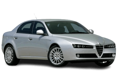
The Alfa Romeo 159 is a mid-size vehicle produced by the Italian automaker from 2005 to 2011. It was offered in both sedan and station wagon (Sportwagon) body styles, sharing a common platform with the Brera and Spider models. The vehicle underwent a facelift in 2008. In this technical article, we provide a detailed overview of the fuse box diagrams for the Alfa Romeo 159 (Type 939A) covering model years 2005 through 2012.
Below, you will find the locations and images of the power distribution boxes. The fuses protecting the “Cigarette Lighter” and “Fuel Pump” circuits are highlighted in bold.
Luggage Compartment
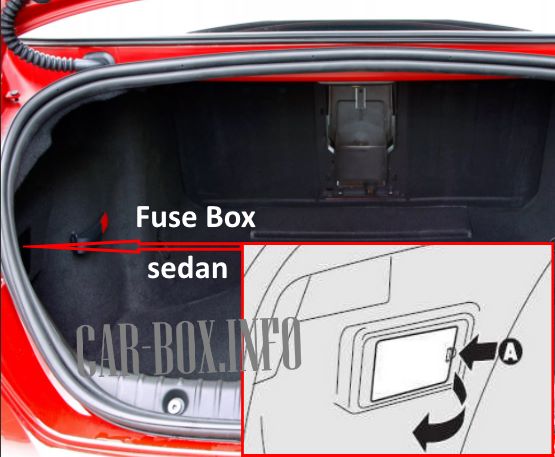
Sedan: Located on the left side of the luggage compartment, behind the access panel.
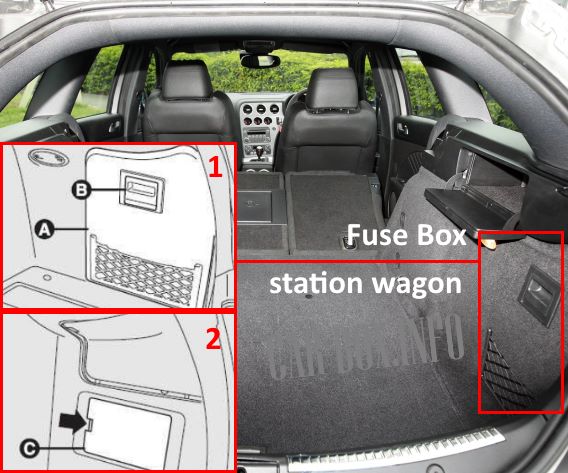
Station wagon: Located on the right side. To access, use the handle (B) to remove the cover, then open the access panel (C).
| Diagram | ||
|---|---|---|
|
||
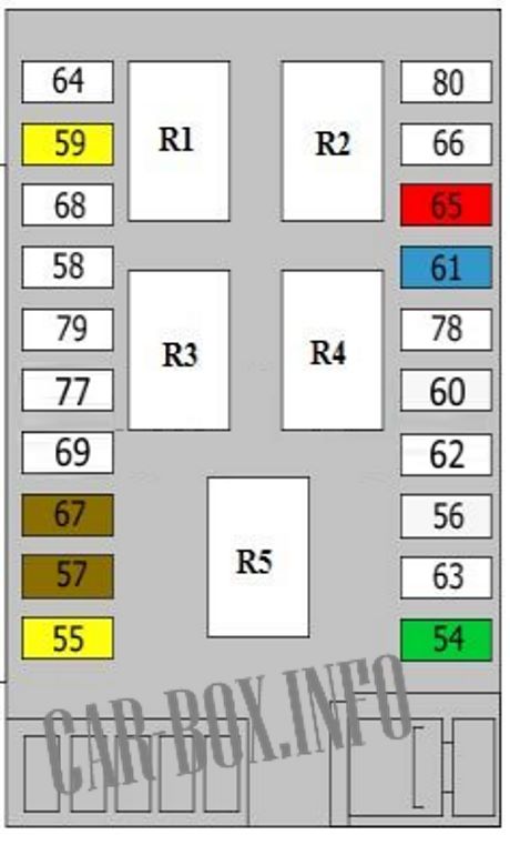
| No. | Description | A |
| 54 | Audio amplifier | 30 |
| 55 | Luggage compartment accessory power connector | 15 |
| 56 | Driver's power seat module | 25 |
| 57 | Front left heated seat | 7.5 |
| 59 | Heated windshield | 20 |
| 60 | Passenger's power seat module | 25 |
| 61 | Audio amplifier | 15 |
| 65 | Automated manual transmission (Selespeed) control module | 10 |
| 67 | Front right heated seat | 7.5 |
| R4 | Rear window defogger relay | |
| R5 | Power outlets, heated seats relay | |
Passenger Compartment

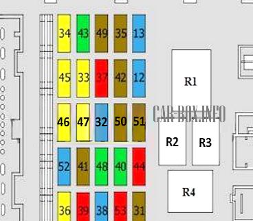
The interior fuse box is located at the lower left of the dashboard, behind the trim panel. To access the fuses, remove the screw (A) and detach the cover panel (B).
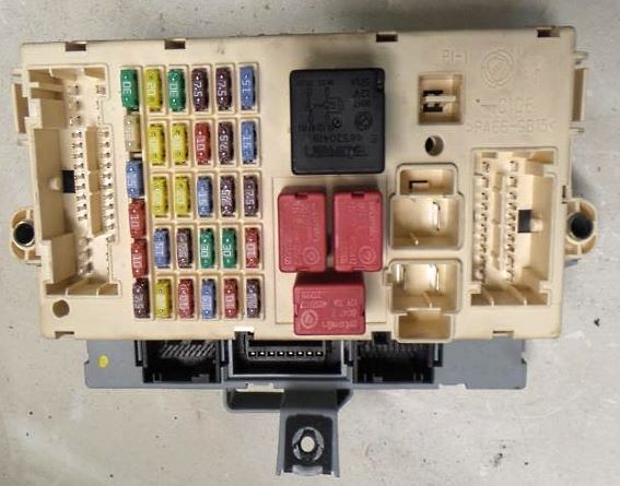
General view of the Alfa Romeo 159 passenger compartment fuse box.
| Diagram | ||
|---|---|---|
|
||
| No. | Description | A |
| 12 | Low beam, right headlight | 15 |
| 13 | Low beam, left headlight | 15 |
| 31 | Ignition coils | 7.5 |
| 32 | Door control module, immobilizer | 15 |
| 33 | Rear left power window motor | 20 |
| 34 | Rear right power window motor | 20 |
| 35 | Reverse lights, cruise control | 7.5 |
| 36 | Luggage compartment control module / front door control module power supply | 20 |
| 37 | Instrument cluster control module, headlight control module / High-Intensity Discharge (Bi-xenon) lighting module power supply (if equipped) | 10 |
| 38 | Rear doors / luggage compartment release actuator | 15 |
| 39 | OBD-II diagnostic connector, Tire Pressure Monitoring System (TPMS) module, mobile phone pre-wiring, warning chime module (if equipped), HVAC control module | 10 |
| 40 | Rear window defogger | 30 |
| 41 | Heated windshield washer nozzles, heated exterior mirrors | 7.5 |
| 42 | Anti-lock Braking System (ABS) module | 7.5 |
| 43 | Windshield wipers / washer pump | 30 |
| 44 | Cigarette lighter | 10 |
| 45 | Spare | 20 |
| 46 | Power sunroof | 20 |
| 47 | Driver's door control module | 20 |
| 48 | Passenger's door control module | 30 |
| 49 | Power sunroof, overhead console, volumetric alarm module, parking assist control module, illuminated front seat controls, START/STOP button, telematics / phone module | 7.5 |
| 50 | Supplemental Restraint System (SRS) / Airbag module | 7.5 |
| 51 | Audio system power supply | 7.5 |
| 52 | Rear window wiper/washer, rear power outlet | 15 |
| 53 | Instrument cluster electronics | 10 |
| R1 | Load reduction relay (Ignition) | |
| R2 | Rear window defogger relay | |
| R3 | Load reduction relay (Ignition) | |
| R4 | Low beam relay | |
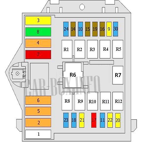
Engine Compartment
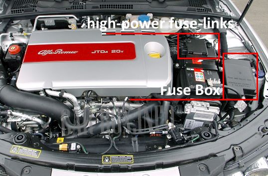
The main power distribution box is located adjacent to the battery. Additionally, a panel of high-amperage maxi fuses is mounted directly on the positive battery terminal.
Main Fuse Box
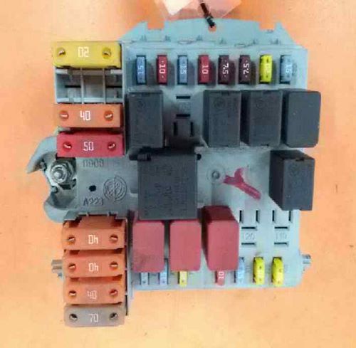
Example of the main fuse box layout.
| Diagram | ||
|---|---|---|
|
||
| No. | Description | A |
| 1 | Passenger compartment fuse box power supply | 70 |
| 2 | HVAC blower motor | 40 |
| 3 | Electronic steering column lock module | 20 |
| 4 | Anti-lock Braking System (ABS) pump / valves | 40 |
| 5 | 40 | |
| 6 | Radiator cooling fan (Low speed) | 40 |
| 7 | Radiator cooling fan (High speed) | 50 |
| 8 | Automated manual transmission (Selespeed) control module | 30 |
| 9 | Headlight washer pump | 20 |
| 10 | Dual-tone horn | 15 |
| 11 | Engine Control Module (ECM) | 15 |
| 14 | High beam, right headlight | 10 |
| 15 | High beam, left headlight | 10 |
| 16 | Engine Control Module (ECM) | |
| 17 | 10 | |
| 18 | Engine Control Module (ECM), automated manual transmission | 15 |
| 19 | A/C compressor clutch | 7.5 |
| 20 | Heated windshield | 20 |
| 21 | Fuel pump | 20 |
| 22 | Ignition coils / fuel injectors | 15/20 |
| 23 | Audio system power supply | 15 |
| 24 | Automated manual transmission (Selespeed) | 15 |
| 30 | Front fog lights | 15 |
| No. | Relay modules | |
| R2 | High beam relay | |
| R8 | Bypass jumper / connector | |
| R3 | Horn relay | |
| R7 | Radiator cooling fan relay (High speed) | |
| R5 | A/C compressor clutch relay | |
| R6 | Radiator cooling fan relay (Low speed) | |
| R9 | Engine Control Module (ECM) main relay | |
| R10 | Fuel pump relay | |
| R14 | Front fog lights relay | |
| R17 | Headlight washer relay | |
| R19 | Heated windshield relay | |
| R20 | Reverse lights relay | |
Battery Distribution Panel
Located on the positive battery terminal.
| Diagram | ||
|---|---|---|

|
||
| F70 | Engine compartment fuse box power supply | 150 |
| F71 | Passenger compartment fuse box power supply | 70 |
| F72 | Spare | 60 |
| F73 | Glow plug control module (Diesel engines) | 60 |
