
The Chevrolet Orlando (J309) is a family vehicle built on a shared platform with the Chevrolet Cruze. It was marketed for model years 2010 through 2018.

This guide provides detailed information on the Chevrolet Orlando electrical circuits, alongside a comprehensive description of all fuse and relay blocks. It also identifies the cigarette lighter fuse and outlines the replacement procedure.
Engine Compartment
Main Fuse Block
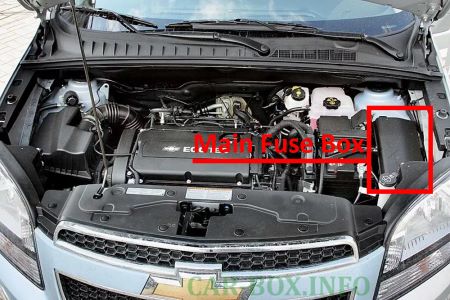
It is located on the left-hand side of the engine compartment, adjacent to the battery.
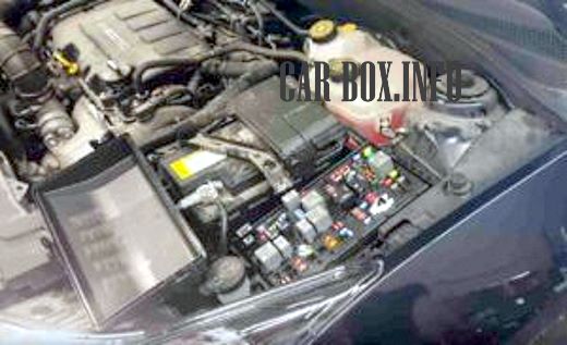
To gain access, disengage the three retaining clips on the cover and remove it.
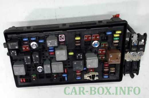
General view of the underhood fuse block.
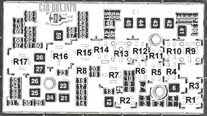
| Diagram | ||
|---|---|---|
|
||
| No. | Rating (A) | Description |
| 1 | 15 | Transmission Control Module (TCM) |
| 2 | 15 | Engine Control Module (ECM) |
| 3 | - | Not Used |
| 5 | 15 | Transmission Control Module (TCM), Engine Control Module (ECM), Mass Airflow (MAF) / Intake Air Temperature (IAT) Sensor, Transmission Output Shaft Speed Sensor |
| 6 | 30 | Windshield Wiper Relay |
| 7 | - | Not Used |
| 8 | 15 | Fuel Injectors |
| 9 | 15 | Ignition Coils, Fuel Injectors |
| 10 | 15 | Engine Control Module (ECM), Transmission Output Shaft Speed Sensor |
| 11 | 10 | Heated Oxygen Sensors (HO2S) |
| 12 | 30 | Starter Motor |
| 13 | 7.5 | Evaporative Emission (EVAP) Canister Vent Solenoid Valve |
| 14 | - | Not Used |
| 15 | - | Not Used |
| 16 | 7.5 | Air Quality Sensor |
| 17 | 5 | Airbag Sensing and Diagnostic Module (SDM) |
| 18 | 10 | Fuel Pump Power Module |
| 19 | - | Not Used |
| 20 | 20 | Fuel Pump Relay |
| 21 | 30 | Front Power Window Motors |
| 22 | - | Not Used |
| 23 | - | Not Used |
| 24 | 30 | Front Power Window Motors |
| 25 | - | Not Used |
| 26 | 40 | Electronic Brake Control Module (EBCM) |
| 27 | 30 | Remote Keyless Entry (RKE) Receiver |
| 28 | 40 | Rear Window Defogger Grid |
| 29 | - | Not Used |
| 30 | 15 | Electronic Brake Control Module (EBCM) |
| 31 | 20 | Body Control Module (BCM) |
| 32 | 20 | Body Control Module (BCM) |
| 33 | 30 | Heated Seat Control Module |
| 34 | 25 | Sunroof Control Module |
| 35 | 30 | Audio Amplifier |
| 36 | - | Not Used |
| 37 | 10 | Headlamp — Right High Beam |
| 38 | 10 | Headlamp — Left High Beam |
| 39 | - | Not Used |
| 40 | - | Not Used |
| 41 | - | Not Used |
| 42 | 20/30 | Cooling Fan Relay, Cooling Fan Motor |
| 43 | - | Not Used |
| 44 | - | Not Used |
| 45 | 30/40 | Cooling Fan High-Speed Relay, Cooling Fan Motor |
| 46 | 10 | Cooling Fan Relay |
| 47 | 10 | Heated Oxygen Sensors (HO2S), Electronic Throttle Body |
| 48 | 15 | Front Fog Lamps |
| 49 | - | Not Used |
| 50 | - | Not Used |
| 51 | 15 | Horn |
| 52 | 5 | Instrument Cluster |
| 53 | 10 | Inside Rearview Mirror |
| 54 | 5 | Headlamp Switch, Auxiliary Electric Heater, Heating, Ventilation, and Air Conditioning (HVAC) Control Module |
| 55 | 7.5 | Front Power Window Switches, Power Mirror Switch |
| 56 | 15 | Windshield Washer Pump |
| 57 | 15 | Steering Column Lock Control Module |
| 58 | - | Not Used |
| 59 | 30 | Fuel Heater |
| 60 | 7.5 | Outside Power Mirrors |
| 61 | - | Not Used |
| 62 | 10 | A/C Compressor Clutch Relay, A/C Compressor Clutch |
| 63 | - | Not Used |
| 64 | 5 | Airbag Sensing and Diagnostic Module (SDM) |
| 65 | - | Not Used |
| 66 | - | Not Used |
| 67 | 20 | Fuel Pump Power Module |
| 68 | - | Not Used |
| 69 | 5 | Body Control Module (BCM) |
| 70 | 5 | Rain Sensor |
| 71 | - | Not Used |
| Relays | ||
| R1 | A/C Compressor Clutch | |
| R2 | Starter Motor | |
| R3 | Cooling Fan | |
| R4 | Windshield Wiper Speed Control | |
| R5 | Windshield Wiper | |
| R6 | Not Used | |
| R7 | Transmission | |
| R8 | Fuel Pump | |
| R9 | Cooling Fan 1 Mid-Speed | |
| R10 | Cooling Fan 2 Mid-Speed | |
| R11 | Not Used | |
| R12 | Cooling Fan Speed Control (or in Auxiliary Relay Block) | |
| R13 | Cooling Fan High-Speed Relay | |
| R14 | Not Used | |
| R15 | Main Ignition (Run/Crank) Relay | |
| R16 | Fuel Heater Relay | |
| R17 | Rear Window Defogger | |
| Note: The relays listed below are non-serviceable printed circuit board (PCB) relays located internally within the block. | ||
| - | Horn Relay | |
| - | Windshield Washer Pump Relay | |
| - | Front Fog Lamp Relay | |
| - | Headlamp High Beam Relay | |
High-Current Fuse Block
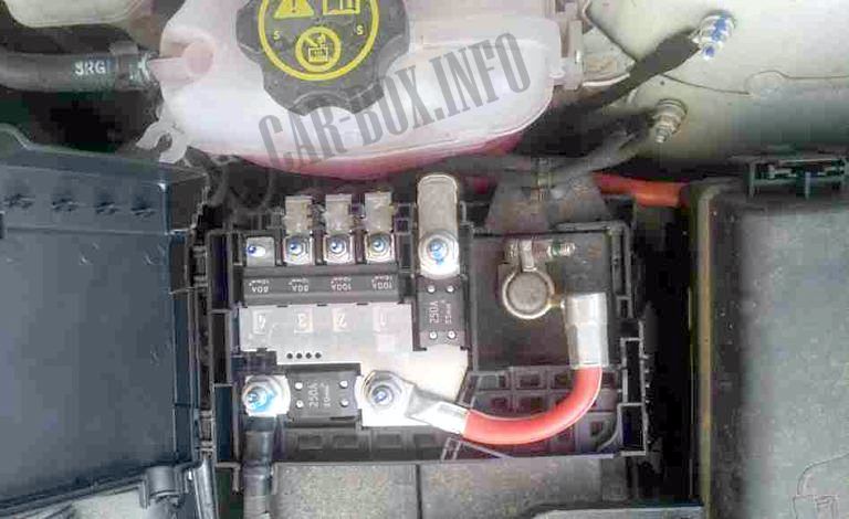
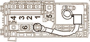
It is mounted on top of the battery cover.
| Diagram | ||
|---|---|---|
|
||
| No. | Rating (A) | Description |
| 1 | 100 | Instrument Panel Fuse Block |
| 2 | 100 | |
| 3 | 80 | Electronic Power Steering (EPS) (NJ1) |
| 4 | - | Not Used |
| 5 | 250 | Auxiliary Battery Fuse Block |
| 6 | 250/500 | Starter Motor |
Auxiliary Relay Block
Depending on the vehicle trim and configuration, an auxiliary relay block may be located within the engine compartment.
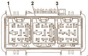
1 — Cooling Fan Low-Speed Relay;
2 — Cooling Fan Low-Speed Relay;
3 — Cooling Fan Speed Control Relay.
Passenger Compartment
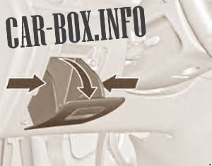
The instrument panel fuse block is located behind the glove box within the dashboard.
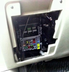
To gain access, compress the sides of the glove box bin, then pull and lift upward to remove it.
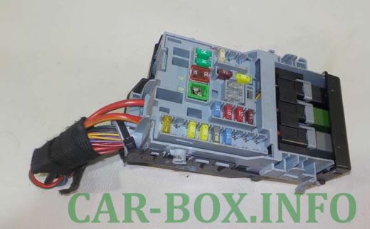
General view of the instrument panel fuse block.
| Diagram | ||
|---|---|---|

|
||
| No. | Rating (A) | Description |
| 1 | - | Not Used |
| 2 | - | Not Used |
| 3 | 25 | Body Control Module (BCM) |
| 4 | 20 | Radio / Infotainment System |
| 5 | 7.5 | Parking Assist Control Module, Audible Warning Chime, Steering Column Switch Assembly, Center Console Display |
| 6 | 20 | Cigarette Lighter |
| 7 | 20 | Power Outlet |
| 8 | 30 | Body Control Module (BCM) |
| 9 | 30 | Body Control Module (BCM) |
| 10 | 30 | Body Control Module (BCM) |
| 11 | 40 | Door Control Module, Blower Motor |
| 12 | - | Not Used |
| 13 | 25 | Heated Seat Control Module |
| 14 | 7.5 | Data Link Connector (DLC), Oil Supply Control |
| 15 | 10 | Airbag Sensing and Diagnostic Module (SDM) |
| 16 | 10 | Liftgate Latch Release Relay |
| 17 | 15 | HVAC Control Module / HVAC Control Panel Assembly |
| 18 | - | Not Used |
| 19 | - | Not Used |
| 20 | - | Not Used |
| 21 | 15 | Instrument Cluster |
| 22 | 2 | Ignition Switch |
| 23 | 20 | Body Control Module (BCM) |
| 24 | 20 | Body Control Module (BCM) |
| 25 | - | Not Used |
| 26 | 20 | Auxiliary Power Outlet |
Internal Relays:
— Liftgate Release;
— Transport / Logistics Mode;
— Auxiliary Power Supply.
