Table of Contents
In this article, we will take a detailed look at the fuse diagrams for the Chrysler Sebring (third generation; JS): 2006, 2007, 2008, 2009, and 2010 model year.

Fuses #11, #13 and #16 in the engine bay block are responsible for the cigarette lighter.
In the engine compartment
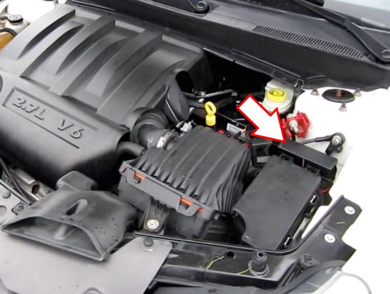
The fuse box and relay box are located here.
Fuse Box
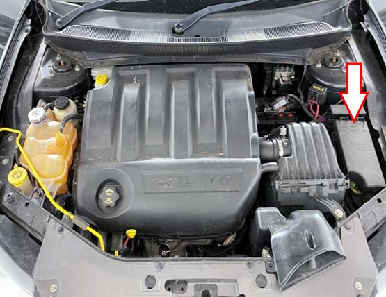
Located near the air cleaner assembly, under the protection cover.
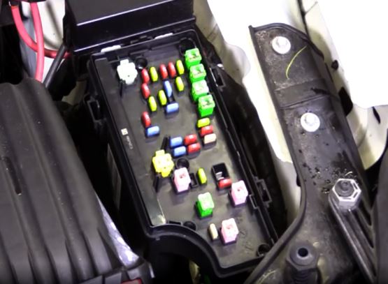
Access example.
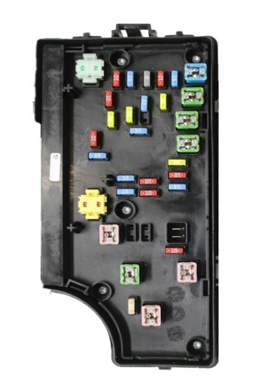
General view.
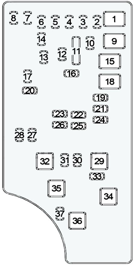
| Diagram | ||
|---|---|---|
|
||
| No. | Description | Amps |
| 1 | Convertible: Power Top Module | 40 |
| 2 | AWD: All Wheel Drive System | 20 |
| 3 | Brake Switch,Center High Mounted Stop Light Lamp | 10 |
| 4 | Ignition Switch | 10 |
| 5 | Trailer Tow | 20 |
| 6 | Satellite Digital Radio (SDAR), Steering Control Module, IOD Switch, Power Mirror Switch, Climate Control System, Hands Free System | 10 |
| 7 | IOD - Ignition Off Draw Sense #1 | 30 |
| 8 | IOD - Ignition Off Draw Sense #2 | 30 |
| 9 | Secondary Air Pump (PZEV), Driver and Passenger Seat Switch | 40 |
| 10 | Cluster, Interior Power Locks | 20 |
| 11 | Power Socket - Console | 15 |
| 12 | Inverter | 20 |
| 13 | Rear Power Socket | 20 |
| 14 | Interior Lighting, Intruson Transceiver Module, Cabin Compartment Node (CCN), Cluster | 10 |
| 15 | Radiator Fan Low or High Speed Relay, Radiator Fan Medium or High Speed Relay | 40 |
| 16 | Moonroof, Power Socket in the Instrument Panel, Chrysler Sebring cigarette lighter fuse | 15 |
| 17 | Sentry Key Remote Entry System, Steering Control Module (SCM), Wireless Control Module (WCM), Clock | 10 |
| 18 | Main Relay | 40 |
| 19 | DVD Video Screen Module, Audio Amp #1 & #2 | 20 |
| 20 | Hands Free System, Radio | 15 |
| 21 | Siren, Intrus Mod | 10 |
| 22 | Climate Control System, Cup Holder Assembly, Compass Sensor | 10 |
| 23 | Main Relay - Feed #3 | 15 |
| 24 | Sedan - Moonroof Motor Convertible - Power Top Module |
25 |
| 25 | Heated Mirrors | 10 |
| 26 | Main Relay - Feed #2 | 15 |
| 27 | Occupant Classification Module, Occupant Restraint Controller | 10 |
| 28 | 10 | |
| 29 | Empty | - |
| 30 | Heated Seats | 20 |
| 31 | Headlight Washer Relay Control Unit | 10 |
| 32 | Main Relay - Feed #1 | 30 |
| 33 | Radiator Fan Low Speed or High Speed Relay, Powertrain Control Module, ABS, Bank Switch, Main Relay, Radiator Fan Series or Parallel Relay, Diagnostic Link Connector, Radiator Fan Medium Speed or High Speed Relay | 10 |
| 34 | Electronic Stability Control System, Anti-Lock Brakes System | 30 |
| 35 | 40 | |
| 36 | Driver Door Module (DDM), Headlamp Washer Control Unit, Passenger Door Module (PDM) | 30 |
| 37 | Inverter 110V | 15 |
| Power Top Module (Convertible) | 25 | |
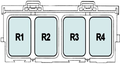
Relay Box
Located near the fuse box.
| Diagram | |
|---|---|
|
|
| R1 | Main Relay - Auto Shutdown |
| R2 | Low or High Speed Radiator Fan Relay |
| R3 | Medium or High Speed Radiator Fan Relay |
| R4 | Series or Parallel Radiator Fan Relay |
View and print PDF:
