
The Berlingo is a popular M-segment compact MPV and panel van from the French automaker Citroën. In this article, we will detail the fuse box diagrams for the 3rd generation Citroën Berlingo (K9 body; EMP2 platform): 2018, 2019, 2020, 2021, 2022, 2023, and 2024 model years.
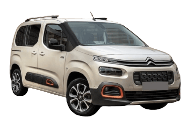
Here you will find the locations and photos of the power distribution boxes. We will specifically highlight the fuses responsible for the cigarette lighter and fuel pump.
Passenger Compartment
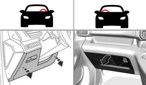
Regardless of the steering wheel position (LHD/RHD), the main fuse box is located on the left side in the lower part of the dashboard.
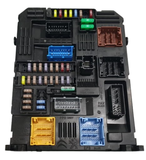
General view.
| Diagram | |
|---|---|
|
|
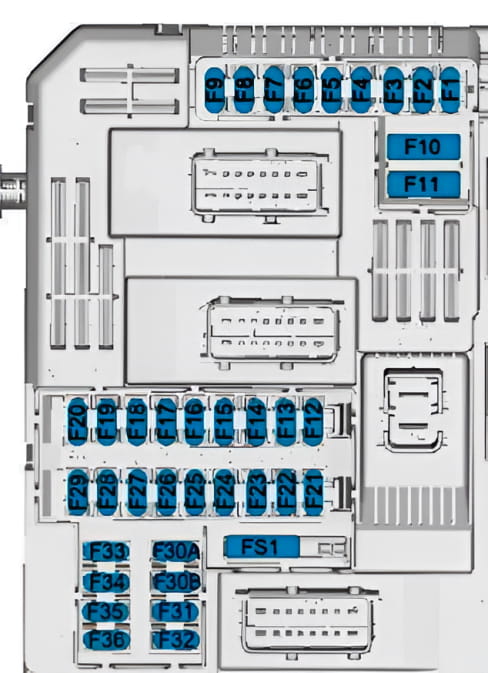
| No. | Protected Circuit |
| 1 | Wireless charging module, auto-dimming rearview mirror, Electric Power Steering (EPS), drive mode selector (Grip Control), front radar, SCR (AdBlue) system ECU |
| 3 | Smartphone wireless charger |
| 4 | Horn |
| 5 | Windshield and rear window washer pump |
| 6 | Windshield and rear window washer pump |
| 7 | Rear USB ports |
| 8 | Rear window wiper motor |
| 10 | Central locking (doors and tailgate) |
| 11 | Central locking (doors and tailgate) |
| 12 | Start-Stop system ECU, OBD-II diagnostic connector, ABS/ESP system ECU |
| 13 | Infotainment system, climate control panel |
| 14 | Factory anti-theft alarm siren |
| 15 | Transmission Control Module (TCM), instrument cluster, climate control module |
| 16 | Start-Stop system ECU, ABS/ESP system ECU |
| 17 | Instrument cluster |
| 18 | Parking assist system ECU |
| 19 | Steering column switch module, steering wheel control buttons |
| 21 | Factory anti-theft alarm module |
| 22 | Windshield-mounted driver assistance camera, rain and light sensor |
| 23 | Unfastened seat belt indicator, Start-Stop ECU, trailer tow hitch module |
| 24 | 7" touchscreen display, automatic parking system, surround-view cameras |
| 25 | Airbag Control Module (SRS) |
| 26 | Electronic Stability Program (ESP) |
| 27 | Alarm system, parking heater control module (Webasto) |
| 28 | Telematics control unit (OnStar / BTA / ERA-GLONASS) |
| 29 | Infotainment system (head unit) |
| 32 | Cigarette lighter / 12 V front power outlet |
| 34 | Auto-dimming rearview mirror, parking assist system |
| 35 | Light switch module, OBD-II connector, climate control panel |
| 36 | Interior lighting (dome lights), front USB ports |
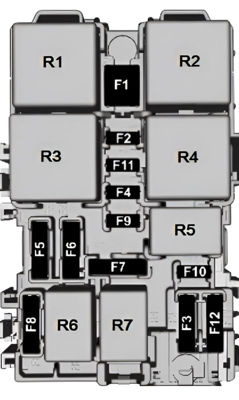
The auxiliary interior fuse and relay box is located behind the main block.
| Diagram | |
|---|---|
|
|
| No. | Protected Circuit |
| F1 | Rear window defogger |
| F2 | Heated exterior mirrors |
| F3 | Front power windows |
| F4 | Exterior mirror power adjustment and folding |
| F5 | Rear power windows |
| F6 | 12 V power outlet in the luggage compartment, power sunroof |
| F7 | Spare |
| F8 | Right dashboard fuse box power supply |
| F9 | Spare |
| F10 | Heated front seats |
| F11 | Front seat massage function |
| F12 | Factory audio system amplifier (Hi-Fi) |
| Relay Modules | |
| R01 | Heated seat relay |
| R02 | Power window relay |
| R03 | Rear window defogger relay |
| R04–R07 | Spare |
Engine Compartment
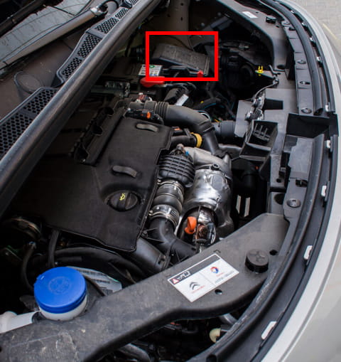
The fuse box is located near the battery.
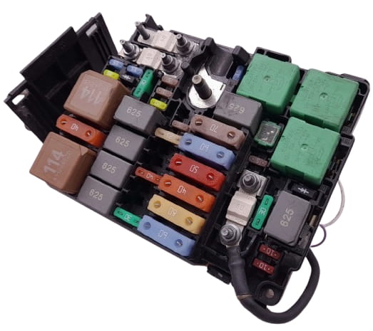
General view.
| Diagram | ||
|---|---|---|
|
||
| No. | Assignment | Rating (A) |
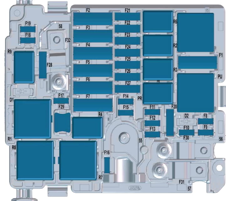
| F1 | HVAC blower motor | 40 |
| F2 | ABS/ESP pump motor | 60 |
| F3 | Passenger compartment fuse box No. 3 power supply | 80 |
| F4 | ABS/ESP hydraulic unit valves | 30 |
| F5 | 50 A: BSI module (right turn signals, right front position lights, right brake lights, left reverse light, right fog light) 20 A: Heated windshield |
50 / 20 |
| F6 | 60 A: Two-speed radiator cooling fan control module (GMV) 20 A: Transmission Control Module (Aisin EAT8 / EAT6) |
60 / 20 |
| F7 | Built-in Systems Interface (BSI) | 70 |
| F8 | 15 A (EP6): Fuel pump, electronic thermostat, oil pump valve, EVAP purge valve, MAF sensor, oxygen sensors (lambda probes) 20 A (EB2 / DV6 / DW10): Engine ECU, fuel lift pump |
15 / 20 |
| F9 | Fuel lift pump (DW10F), VVT solenoids, electronic thermostat, oil pump valve, EVAP purge valve, MAF sensor, oxygen sensors (EP6), electric water pump | 15 |
| F10 | Engine ECU, HPFP metering unit, turbocharger geometry control valve (DV5R / DW10F), electronic thermostat (DV5R), PCV heater, VVT solenoids (EP6), EVAP purge valve, upstream oxygen sensor (EB2) | 15 |
| F11 | Engine ECU | 20 |
| F12 | Instrument cluster, cooling fan relay (GMV), Start-Stop system (i-StARS), turbocharger electric coolant pump, Built-in Systems Interface (BSI) | 5 |
| F13 | Built-in Systems Interface (BSI) | 5 |
| F14 | Battery charge status module (IBS / BECB) | 5 |
| F15 | Heated windshield | 20 |
| F16 | Fog lights (15 A) / Daytime Running Lights (10 A) | 10 / 15 |
| F17 | BFRM relay diagnostic circuit, BSI module, Engine ECU, downstream NOx sensor (DV5R / DW10) | 10 |
| F18 | Right high beam headlight | 10 |
| F19 | Left high beam headlight | 10 |
| F20 | Engine ECU, fuel lift pump, ignition coils | 30 |
| F21 | Starter motor solenoid | 30 |
| F22 | Spare / Taxi equipment | 40 |
| F23 | Starter / Alternator | 40 |
| F24 | Passenger compartment fuse box No. 5 power supply | 40 |
| F25 | Passenger compartment fuse box No. 3 power supply | 40 |
| F26 | Heater blower motor | 15 / 20 |
| F27 | BSI module (right low beam headlight, right reverse lights, left fog light, left rear position light, high-mount stop light / third brake light) | 25 |
| F28 | SCR (AdBlue) pump module and line heater, NOx sensor (DW10F), Engine ECU | 30 |
| F29 | Windshield wiper motor (linkage) | 40 |
| F30 | Glow plug control module (diesel) | 80 |
| F31 | Power distribution and protection module (BPGA) | 80 |
| F32 | Electric Power Steering (EPS), left low beam headlight, adaptive lighting system (cornering lights), side repeaters, left turn signals, left front and right rear position lights, left brake lights, license plate lighting | 80 |
| R1 | Engine ECU main relay / SCR module power supply (Euro 6) | — |
| R2 | A/C compressor clutch / Heated windshield relay | — |
| R3 | Starter relay / Parking heater | — |
| R4 | Fog light / Daytime Running Light (DRL) relay | — |
| R5 | HVAC blower motor relay | — |
| R6 | Starter solenoid relay | — |
| R7 | Windshield wiper relay (low speed) | — |
| R8 | Windshield wiper relay (high speed) | — |
| R9 | Main headlight power relay | — |
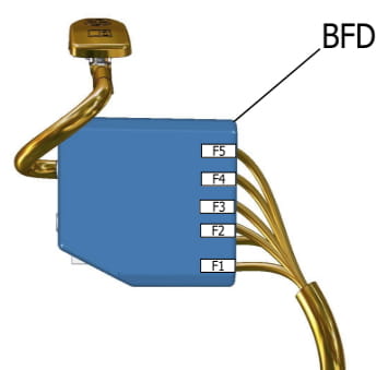
Attached to the positive battery terminal is a panel consisting of high-current fusible links.
| Diagram | ||
|---|---|---|
|
||
| No. | Assignment | Rating (A) |
| 1 | Radiator cooling fan electronic control module | 60 |
| 2 | Main engine compartment fuse box (BSM / PSF1) power supply | 100 |
| 3 | Power steering / Electric Power Steering (EPS) pump motor | 80 |
| 4 | Passenger compartment fuse box (BSI) power supply | 80 |
| 5 | Passenger compartment fuse box (BSI) power supply | 80 |
