Citroen Berlingo belongs to the class of multipurpose vehicles MPV and offers both commercial vans and passenger modifications in its range. At the end of 2002, the model was restyled. In this article, we will take a detailed look at the fuse box diagrams for the Citroen Berlingo (1st generation; body MF; in restyling M59) 2002, 2003, 2004, 2005, 2006, 2007, 2008, 2009, 2009, 2010, 2011, 2012 years of manufacture.
Here you will find the locations and photos of distribution boxes. The fuses responsible for the “Cigarette lighter” and “Fuel Pump” are highlighted in bold.
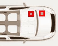
Most of the safety features are in distribution boxes located in the passenger compartment and under the hood.
In the passenger compartment
There are two distribution boxes here that are responsible for protecting the electrical circuits.
Fuse box
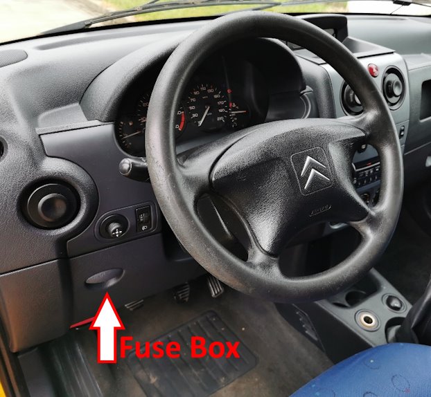
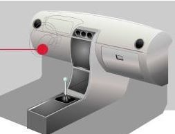
Located on the driver's side, at the bottom of the dashboard.
To access it, you need to remove the protective cover.
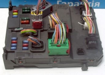
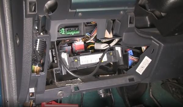
General view of the Citroen Berlingo interior fuse box.
| Diagram | ||
|---|---|---|

|
||
| № | Decoding | Amps |
| 1 | Rear window wiper (with swing doors), 12 V socket (Modutop) | 15 |
| 4 | Car radio instrument cluster, display, COM2000 | 20 |
| 5 | Security alarm siren | 15 |
| 6 | Diagnostic connector | 10 |
| 7 | Alarm system | 15 |
| 9 | Seat heating system, electric fan Modutop | 30 |
| 10 | Electric rear window heating element, electrically heated exterior mirrors | 40 |
| 11 | Rear window wiper | 15 |
| 12 | Power sunroof, power windows | 30 |
| 14 | VAN COM2000 | 10 |
| 15 | VAN network instrument cluster, car radio, display | 15 |
| 16 | Power door locks | 30 |
| 20 | Rear right brake light | 10 |
| 21 | Rear Left Brake Light | 15 |
| 21 | Berlingo cigarette lighter fuse, 12 V socket, power outside mirrors, interior lamps, directional light for reading maps and documents | 20 |
Additional elements on the side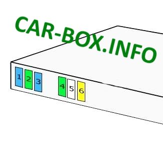
|
||
| 1 | Multiplex System | 15 |
| 2 | Windows / Sunroof | 30 |
| 3 | Air Conditioning Compressor | 15 |
| 4 | Heated mirrors | 30 |
| 5 | Wipers | 25 |
| 6 | Central locking system | 20 |
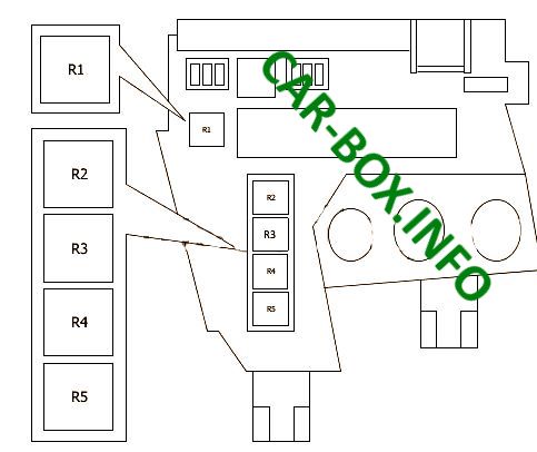
Relay box
| Diagram | |
|---|---|
|
|
| № | Description |
| R1 | Engine relay |
| R2 | Dipped beam relay OR Side beam relay (with daylight system) |
| R3 | Dipped beam |
| R4 | heated seats |
| R5 | Headlight washer |
In the engine compartment
One main unit and separate relay modules are located here.
Fuse box
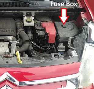
Located on the driver's side behind the protective cover.
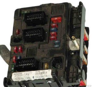
General view.
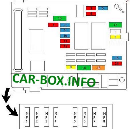
Type 1
The first variant of the underhood unit design.
| Diagram | ||
|---|---|---|
|
||
| No. | Description | Amps |
| 1 | Reverse light switch / Vehicle speed sensor / Clutch pedal position switch | 10 |
| 2 |
|
15 |
| 3 | ABS control unit | 10 |
| 4 |
|
10 |
| 5 | Reserve | - |
| 6 | Front fog lights | 15 |
| 7 | Headlight washer pump | 20 |
| 8 |
|
20 |
| 9 | Left headlight | 15 |
| 10 | Right headlight | 15 |
| 11 | Left headlight | 10 |
| 12 | Right headlight | 10 |
| 13 | Horn (beep) | 15 |
| 14 | Washer pump | 10 |
| 15 |
|
30 |
| 16 | Air pump | 30 |
| 17 | Wipers | 30 |
| 18 | blower | 40 |
| MF1 | Cooling Fan | 20/80 |
| MF2 | ABS module | 20/80 |
| MF3 | Reserve | |
| MF4 | Interior fuse box | 20/80 |
| MF5 | 20/80 | |
| MF6 | Reserve | 20/80 |
| MF7 | Ignition switch | 20/80 |
| MF8 | Reserve | - |
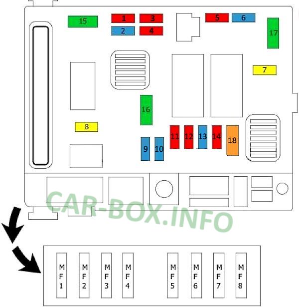
Type 2
Fuses assignment.
| Diagram | ||
|---|---|---|
|
||
| No. | Description | Amps |
| 1 | Back-up lamp, preheater unit, clutch release contact | 10 |
| 2 | Fuel pump fuse | 15 |
| 3 | ABS ECU | 10 |
| 4 | Engine ECU | 10 |
| 5 | Reserve | 10 |
| 6 | Front fog lights | 15 |
| 7 | Headlight washer | 20 |
| 8 | Engine ECU, fan relay | 20 |
| 9 | Left low beam headlamp | 15 |
| 10 | Right low beam headlamp | 15 |
| 11 | Left high beam headlamp | 10 |
| 12 | High beam headlight, right | 10 |
| 13 | Horn (beep) | 15 |
| 14 | Windscreen washer | 10 |
| 15 | Engine sensors | 30 |
| 16 | Air pump | 30 |
| 17 | Windshield wiper | 30 |
| 18 | Electric fan of the climate control system | 40 |
| MF1 | Cooling fan relay | |
| MF2 | ESP / ABS control unit (hydraulic unit) | |
| MF3 | Not used | |
| MF4 | BSI | |
| MF5 | ||
| MF6 | Not used | |
| MF7 | Ignition switch | |
| MF8 | Not used | |
Individual relays

Some relay modules can be located separately:
R1 - Main relay;
R2 - ABS / ESP;
R3 - Air pump relay.
