Citroen Berlingo is a minivan for outdoor activities and a commercial van in one body. The model is produced since 1996, the second generation saw the light of day in 2008. The body, still combining a roomy "boxy" rear part with an aerodynamic front, has become slightly larger compared to its predecessor. The car is built on a base common with the C4. In this article, we will take a detailed look at the fuse box diagrams for the Citroen Berlingo (2nd generation; body B9) 2008, 2009, 2009, 2010, 2011, 2011, 2012, 2012, 2013, 2013, 2014, 2015, 2016, 2017, 2018, 2019, 2020 years of manufacture.

Here you will find the locations and photos of distribution boxes. The fuses responsible for the “Cigarette lighter” and “Fuel Pump” are highlighted in bold.
In the engine compartment
There are two distribution boxes here that are responsible for protecting the electrical circuits.
Main fuse box
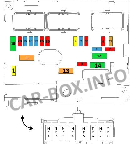
The distribution box is located on the right side of the engine compartment next to the battery. Depending on the version, additional fuses may be located on its side panel.
Type 1
Assignment of the fuses in the engine compartment block of the Berlingo 2.
| Diagram | ||
|---|---|---|
|
||
| No. | Decoding | A |
| 1 | Engine control module | 20 |
| Fan control module | ||
| 2 | Horn (beep) | 15 |
| 3 | Front and rear windshield washers | 10 |
| 4 | Headlight washer / washer system | 20 |
| 5 | Engine management | 15 |
| Fuel (Gasoline) pump fuse | ||
| 6 | ABS / ESP control module | 10 |
| Double relay | ||
| Power steering | ||
| ESP accelerometer gyroscope | ||
| Power steering pump | ||
| 7 | Stop lights | 10 |
| 6 | Launch system | 25 |
| 9 | Protection relay box | 10 |
| Headlight adjustment | ||
| 10 | Engine management | 30 |
| Ignition coil | ||
| Injection control unit | ||
| 11 | Heater fan motor | 40 |
| 12 | Windshield wiper | 30 |
| 13 | Fuses on BSI (Intelligent Power Distribution Module) | 40 |
| 14 | Engine management | 30 |
| Exhaust heat exchanger pump | ||
| 15 | Right headlight - High beam | 10 |
| 16 | Left headlight - High beam | 10 |
| 17 | Left headlight - dipped beam | 15 |
| 18 | Right headlight - dipped beam | 15 |
| 19 | Adsorber purge valve | 15 |
| Oxygen sensor before catalytic converter | ||
| Oxygen sensor behind the catalytic converter | ||
| 20 | Exhaust heat exchanger solenoid valve | 10 |
| 21 | Fan control unit | 5 |
| MF1 | Fan relay | |
| MF2 | Trailer relay | 40/50 |
| Air conditioning relay | ||
| MF3 | Fan | 50 |
| MF4 | BSI (Intelligent Power Distribution Module) | 80 |
| MF5 | BSI (Intelligent Power Distribution Module) | |
| MF6 | ABS engine relay | |
| program stability relay (ESP) | ||
| MF7 | Interior fuse box | 40 |
| MF8 | ABS engine relay | 30 |
| program stability relay (ESP) | ||
Type 2
Fuses assignment.
| Diagram | ||
|---|---|---|
|
||
| No. | Appointment | A |
| F1 | Engine management | 20 |
| F2 | Horn (beep) | 15 |
| F3 | Windshield wiper / washer | 10 |
| F4 | Headlamp washer/wiper system | 20 |
| F5 | Engine management | 15 |
| F6 | steering angle sensor, ESC system | 10 |
| F7 | Stop lights | 10 |
| F8 | Launch system | 25 |
| F9 | headlight control actuator, parktronic ECU | 10 |
| F10 | Engine management | 30 |
| F11 | Heater fan motor | 40 |
| F12 | Windshield wiper | 30 |
| F13 | intelligent switching unit | 40 |
| F14 | Engine management | 30 |
| F15 | Right headlight - High beam | 10 |
| F16 | Left headlight - High beam | 10 |
| F17 | Right headlight - Dipped beam | 15 |
| F18 | Left headlight - Dipped beam | 15 |
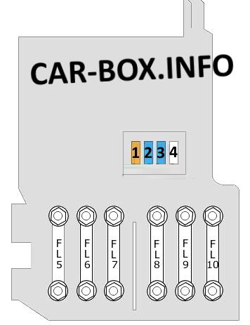
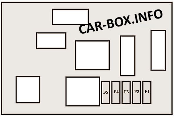
Power fuses
On the battery cover is a board consisting of high-power fusible links and several fuses.
|
||
| No. | Description | A |
| FL5 | Power steering | 80 |
| FL 6 | Glow plugs | 70 |
| FL 7 | Relay 3 trip protection | 100 |
| FL 8 | Stop-start system | |
| FL 9 | - | |
| FL 10 | Engine management | 30 |
| 1 | Charging system | 5 |
| 2 | Diagnostic connector (DLC) | 15 |
| 3 | Stop lights | 15 |
| 4 | - | |
In the passenger compartment
There are three distribution boxes here, which are responsible for protecting the vehicle's electrical circuits.
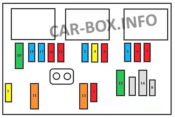
Main fuse box
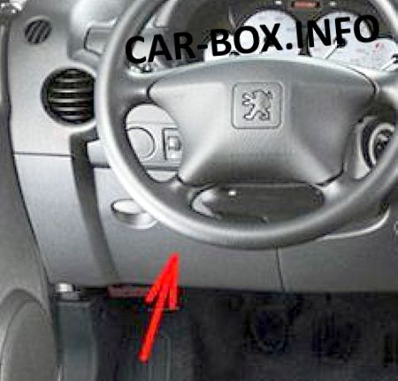
It is located on the driver's side at the bottom of the dashboard. It is covered by a plastic cover.
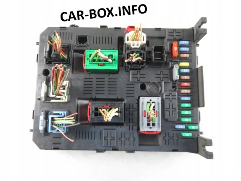
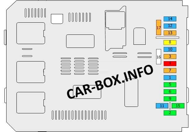
General view of the Citroen Berlingo interior fuse box.
| Diagram | ||
|---|---|---|
|
||
| No. | Description | A |
| 1 | Rear window wiper | 15 |
| 2 | central locking system | 30 |
| 3 | SRS electronic control unit | 5 |
| 4 | Air conditioning, diagnostic socket, rear view mirror, headlight regulator | 10 |
| 5 | Front power windows | 30 |
| 6 | Locks | 30 |
| 7 | Interior light bulbs (tail light, front individual light, sunroof) | 5 |
| 8 | Car radio, display, tire pressure monitoring unit, alarm system and siren | 20 |
| 9 | Berlingo cigarette lighter fuse, 12v sockets front and rear | 30 |
| 10 | central steering column | 15 |
| 11 | Ignition lock | 15 |
| 12 | Rain and light sensor, safety airbags | 15 |
| 13 | Instrument panel | 5 |
| 14 | parking sensors, air conditioning control panel, hands-free system | 15 |
| 15 | central locking system | 30 |
| 16 | Connector (jumper) | |
| 17 | Rear window and mirror heating | 40 |
Additional block #1
There is an additional block next to the main one.

It may consist of the following elements:
1. Empty;
2. Heated seats - 20A ;
3. Empty;
4. Folding rearview mirror relay - 15A;
5. Relay of the socket for connecting the refrigerator compartment - 15A
Additional block #2
An additional coupling block is available as an option. It is located on the right-hand side behind the limiting wall.
|
||
| 1 | Spare | 15 |
| 2 | Ignition, alternator relay | 15 |
| 3 | Trailer power supply 12V | 15 |
| 4 | Constant power supply to transformers | 15 |
| 5 | Emergency signaling lamps | 40 |

Hi Series III multispace. ANy idea which fuse covers the cruise control?