In 2006, a new series of commercial models Citroen Jumper, Peugeot Boxer and Fiat Ducato, developed by Sevel joint venture between Fiat and PSA group, was introduced. In this article, we will take a detailed look at the fuse box diagrams for the Citroen Jumper (2nd generation; with 4H series engines) 2006, 2007, 2008, 2008, 2009, 2009, 2010, 2010, 2011, 2012, 2012, 2013, 2014 years of manufacture.
Here you will find the locations and photos of distribution boxes. The fuses responsible for the “Cigarette lighter” and “Fuel Pump” are highlighted in bold.
In the passenger compartment
There are two distribution boxes here that are responsible for protecting the electrical circuits.
Main fuse box

Located on the driver's side, at the bottom of the dashboard behind the protective cover.
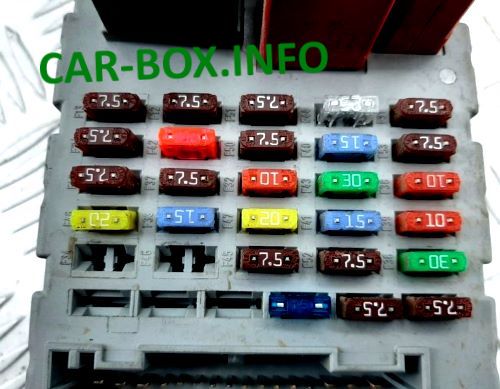
General view of the Citroen Jumper interior fuse box.
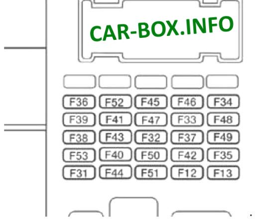
Type 1
Diagram.
|
||
| No. | Description | Amps |
| 12 | Low beam - right bulb | 7.5 |
| 13 | Low beam - left bulb / Headlight corrector | 7.5 |
| 31 | Relay power | 7.5 |
| 32 | Interior lighting - Alarm system | 10 |
| 33 | Rear 12V power outlet | 15 |
| 34 | Empty | - |
| 35 | Back-up lamps - Diesel water sensor | 7.5 |
| 36 | Control unit for unlocking / locking door locks | 20 |
| 36 | Central locking - Battery | 15 |
| 37 | Stop lamp switch - Third brake light - Instrument cluster | 10 |
| 7.5 | ||
| 38 | Electrical relays | 10 |
| 39 | Car radio - Diagnostic connector - Security alarm siren - Programmable heating system controls - Air conditioning control panel - Chronotachograph - Battery | 10 |
| 40 | Heating: rear window (left side), rear view mirror (driver's side) | 15 |
| 41 | Heating: rear window (right side), rearview mirror (passenger side) | 15 |
| 42 |
|
7.5 |
| 43 | Windshield wiper motor | 30 |
| 44 |
|
20 |
| 45 |
|
7.5 |
| 46 | Not | - |
| 47 | Driver's side power window | 20 |
| 48 | Passenger side power window | 20 |
| 49 | Rain/light sensor - Car radio - Driver's side window elevator motor - - Security alarm system - Controls | 7.5 |
| 50 | Airbag and pretensioner ECU | 7.5 |
| 51 | Chronotachograph - Speed controller - Air conditioning control panel | 7.5 |
| 52 | Interior electrical relay | 7.5 |
| 53 | Instrument cluster - Rear fog lights | 7.5 |
Relay elements on the side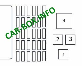
|
||
| 1 | dipped headlights | |
| 2 | Rear window heating | |
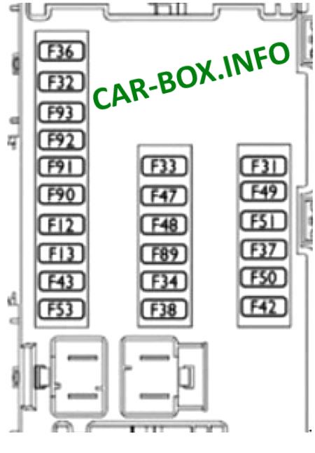
Type 2
Interior fuse box diagram.
|
||
| No. | Decoding | Amps |
| 12 | Right headlight - low beam | 7.5 |
| 13 | Left headlight - low beam | 7.5 |
| 31 | Relay power | 5 |
| 32 | Interior lighting plafond | 7.5 |
| 33 | Battery sensor | 20 |
| 34 | Minibus interior lighting, alarm | 20 |
| 36 | Car radio, diagnostic socket, security alarm siren, auxiliary heating control unit with programming, air conditioning control panel, chronotachograph, battery battery | 10 |
| 37 | Brake Light Switch - Third Brake Light - Instrument Cluster | 7.5 |
| 38 | Central locking switch | 20 |
| 42 | ABS and ESP microprocessor and sensor, brake light switch | 5 |
| 43 | Windshield wiper motor | 20 |
| 47 | Driver's power window | 20 |
| 48 | Passenger power window | 20 |
| 49 | Car radio, controls and driver's seat equipment | 5 |
| 50 | Airbag and belt pretensioner ECU | 7.5 |
| 51 | Chronotachograph, cruise control, A/C control panel, reversing lights, diesel water sensor | five |
| 53 | Instrument cluster | 7.5 |
| 89 | Not | - |
| 90 | High beam left headlight | 7.5 |
| 91 | High beam right headlight | 7.5 |
| 92 | Left fog lights | 7.5 |
| 93 | Right fog lights | 7.5 |
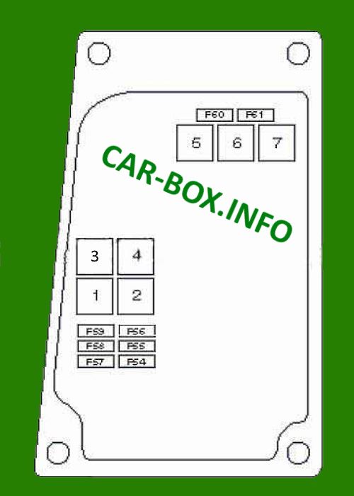
Additional fuse box

Next to the passenger seat there is an additional passenger compartment unit. Its design also has several variants and depends on the year of manufacture and equipment.
| Diagram | ||
|---|---|---|
| Type 1 | ||
|
||
| No. | Appointment | A |
| F54 | Air conditioner / heater | 10 |
| F55 | Seat heater | 15 |
| F56 | 15 | |
| F57 | Air conditioner / heater | 10 |
| F58 | dipped headlights | 10 |
| F59 | Active suspension system | 7.5 |
| F60 | Air conditioner / heater |
10 |
| F61 | 30 | |
| 2 | Cigarette lighter relay | |
| 3 | Parking lamp relay | |
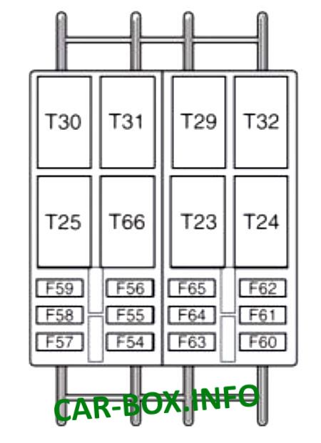
| Type 2 | ||
|
||
| No. | Description | Amps |
| F54 | Not | - |
| F55 | Heated seats | 15 |
| F56 | Electrical outlet near the rear passenger seats | 15 |
| F57 | Additional heater under the seat | 10 |
| F58 | Rear window heater (left) | 10 |
| F59 | Rear window heater (right) | 7.5 |
| F60 | Not | - |
| F61 | Not | - |
| F62 | Not | - |
| F63 | Programmable heating switch | 10 |
| F64 | Not | - |
| F65 | Passenger auxiliary heater fan | 30 |
| T30 | parking light relay | |
| T31 | auxiliary heater relay | |
| T66 | cigarette lighter relay | |
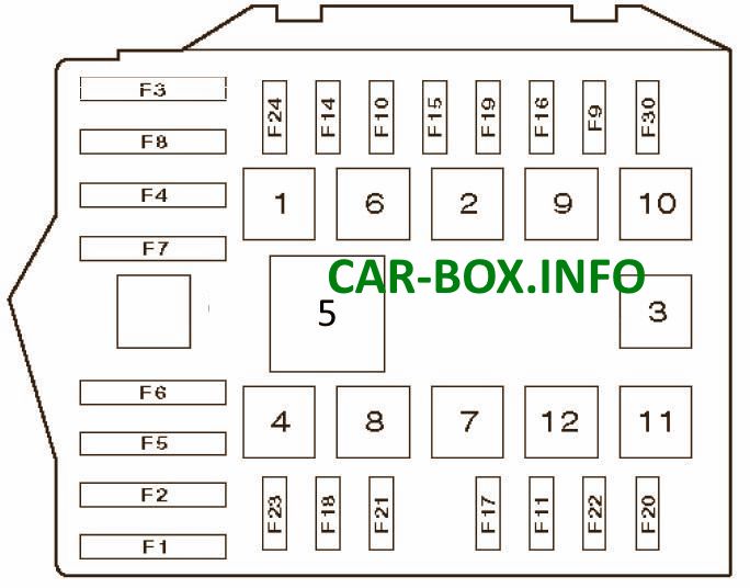
In the engine compartment

Located near the side post.

General view of one of the options.
Type 1
Assigment of fuses and relays.
| Diagram | ||
|---|---|---|
|
||
| No. | Description | Amps |
| F1 | ABS system | 40 |
| F2 | Engine management | 50 |
| F3 | Ignition lock | 30 |
| F4 | Air conditioner / heater | 20 |
| F5 | 20 | |
| F6 | 40/60 | |
| F7 | 40/50 | |
| F8 | Air conditioner / heater | 40 |
| F9 | Headlight washers | 20 |
| F10 | Horn (beep) | 15 |
| F11 | Engine management | 15 |
| F14 | High beam lamp (right) | 7.5 |
| F15 | High beam lamp (left) | 7.5 |
| F16 | Engine management | |
| F17 | Engine management | 10 |
| F18 | ||
| F19 | Air conditioner / heater | |
| F20 | Headlight washers | 30 |
| F21 | Engine management |
15 |
| F22 | 20 | |
| F23 | ABS | 30 |
| F24 | Automatic transmission | 15 |
| F30 | Fog lights | 15 |
| 1 | Headlamp high beam relay | |
| 2 | Horn relay | |
| 3 | Air conditioner compressor solenoid clutch relay | |
| 4 | ||
| 5 | ||
| 6 | Heater fan motor relay | |
| 7 | Engine control relay | |
| 8 | Fuel pump relay | |
| 9 | Fog lamp relay | |
| 10 | Windshield washer pump relay | |
| 11 | Headlight washer / washer relay | |
| 12 | ||
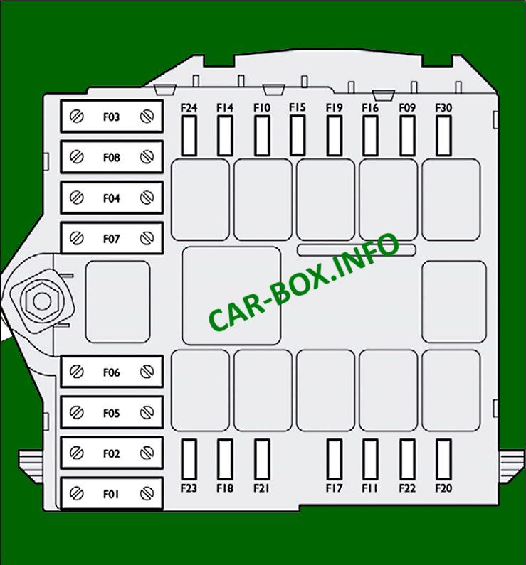
Type 2
Assigment of fuses.
| Diagram | ||
|---|---|---|
|
||
| No. | Purpose (Type 1) | Amps |
| F01 | ABS pump (+ battery) | 40 |
| F02 | Spark plugs (+ battery) | 50 |
| F03 | Ignition switch (+ battery) | 30 |
| F04 | Webasto pre-heater control unit (+ battery) | 20 |
| F05 | Cabin ventilation system with Webasto heater / diesel filter heater (+ battery) | 50 |
| F06 | High-speed engine cooling fan (+ battery) | 40/60 |
| F07 | Low speed engine cooling fan (+ battery) | 40/50 |
| F08 | Interior fan (+ key) | 40 |
| F09 | Windshield washer pump | 20 |
| F10 | Horn (beep) | 15 |
| F11 | Electrical equipment (secondary devices) | 15 |
| F14 | High beam headlight, right | 7.5 |
| F15 | Left high beam headlamp | 7.5 |
| F16 | Electrical equipment (+ key) | 7.5 |
| F17 | Electrical equipment (primary devices) | 10 |
| F18 | Engine control unit (+ battery) | 7.5 |
| F19 | Air conditioning compressor | 7.5 |
| F20 | Headlight washer pump | 30 |
| F21 | Fuel pump fuse | 15 |
| F22 | Electrical equipment (primary devices) | 20 |
| F23 | Solenoid valves in ABS system | 30 |
| F24 | Automatic transmission 8 (+ key) | 15 |
| F30 | Fog lights | 15 |
| No. | Protected circuits (Type 2) | A |
| F1 | ABS pump power supply | 40 |
| F2 | Diesel preheating system ECU | 50 |
| F3 | Ignition switch contact | 30 |
| F4 | Headlight washer pump | 30 |
| F8 | Interior ventilation fan | 40 |
| F9 | Rear 12V power outlet | 15 |
| F10 | Horn | 15 |
| F14 | Front 12V socket, cigarette lighter | 15 |
| F15 | Cigarette lighter | 10 |
| F20 | Windshield washer pump | 30 |
| F21 | Fuel pump power supply circuit | 15 |
| F24 | Additional board for ambulance vehicle, rear view mirrors | 15 |
| F30 | Window heating | 15 |
