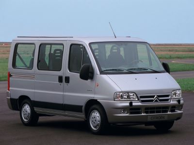
The Citroën Jumper has been produced since February 1994 as a successor to the C25 model. The car was developed by the Sevel joint venture (together with PSA Group). In this article, we will take a detailed look at the fuse box diagrams for the Citroen Jumper (1st generation; bodywork 230 / 244) 1994, 1995, 1996, 1996, 1997, 1998, 1998, 1999, 2000, 2001, 2002, 2003, 2004, 2005, 2006 years of manufacture.
Here you will find the locations and photos of distribution boxes. The fuses responsible for the “Cigarette lighter” and “Fuel Pump” are highlighted in bold.
In the passenger compartment
There are two distribution boxes here that are responsible for protecting the electrical circuits.
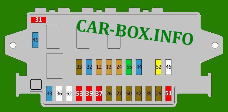
Main fuse box
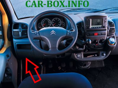
Located on the driver's side behind the dashboard cover.

General view of the Citroen Jumper interior fuse box.
| Diagram | ||
|---|---|---|
|
||
| No. | Decoding | A |
| 12 | Right side light | 5 |
| Right tail light | ||
| 13 | Left side light | 5 |
| Left tail light | ||
| 24 | License plate illumination lamp | 5 |
| Signal lamp, sidelights | ||
| Illumination, instrument panels | ||
| 25 | Audio system | 7.5 |
| 26 | Stop lights | 7.5 |
| 27 | Electric rearview mirror | 7.5 |
| Cruise control | ||
| telephone | ||
| Tachograph | ||
| Remote control | ||
| Alarm | ||
| 31 | Lighting control switch | 10 |
| 32 | Audio system | 15 |
| 33 | Fog lights | 7.5 |
| 35 | Power window controls | 7.5 |
| 37 | Instrument panel illumination | 10 |
| 39 | Interior lighting | 10 |
| Diagnostic connector | ||
| 42 | ABS control unit | 7.5 |
| 43 | Windshield washer | 15 |
| 44 | Cigarette lighter fuse jumper | 15 |
| 49 | Headlight washers | 15 |
| 50 | Airbag control unit | 7.5 |
| 51 | Not | 10 |
| 52 | 12V power outlet | 20 |
| 53 | Direction indicators | 10 |
| Alarm | ||
| Instrument panel illumination | ||
| 55 | Blower, auxiliary heater | 30 |
| Additional heater | ||
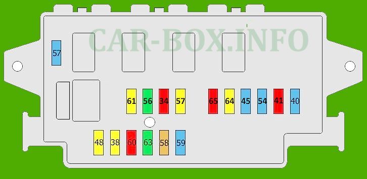
Additional fuse box

The add-on unit is located on the passenger side under the dashboard.
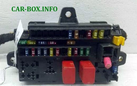
The photo shows an example.
| Diagram | ||
|---|---|---|
|
||
| No. | Description | A |
| 34 | Tachograph | 10 |
| Telephone | ||
| Alarm | ||
| Remote control | ||
| 38 | central locking system | 20 |
| 40 | Rear window heater, right side | 15 |
| 41 | Heated rearview mirror | 10 |
| 45 | Heated seats | 15 |
| 47 | Front left power window | 20 |
| 48 | Front right power window | 20 |
| 54 | Rear window heater, left side | 15 |
| 56 | Additional air conditioner | 30 |
| 57 | Blower, auxiliary heater | 15 |
| 58 | Auxiliary heater programmer | 5 |
| 59 | Shelf (supply) | 15 |
| 60 | Alarm | 10 |
| 61 | Additional heater | 20 |
| 63 | Special equipment | 30 |
| 64 | 20 | |
| 65 | Accessory connector | 10 |
In the engine compartment
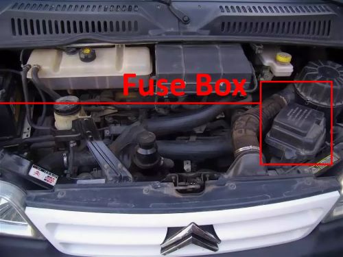
Fuse box located on the left side of the engine compartment.
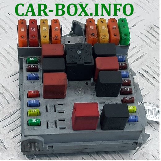
General view.
| Diagram | ||
|---|---|---|
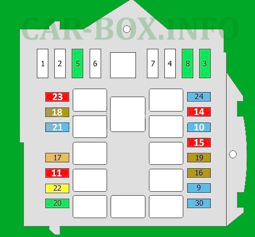
|
||
| No. | Description | A |
| 1 | Unknown | 60 |
| 2 | Unknown | 50 |
| 3 | Unknown | 30 |
| 4 | Unknown | 50 |
| 5 | Unknown | 30 |
| 6 | Unknown | 70 |
| 7 | Unknown | 70 |
| 8 | Unknown | 30 |
| 9 | Front fog lights | 15 |
| 10 | Warning system | 15 |
| Steering wheel controls | ||
| 11 | The engine control unit | 10 |
| Engine electronics | ||
| 14 | Right dipped beam | 10 |
| 15 | Left dipped beam | 10 |
| 16 | Not used | 7.5 |
| 17 | engine control unit | 7.5 |
| Engine electronics | ||
| 18 | engine control unit | 7.5 |
| Engine electronics | ||
| 19 | Compressor | 7.5 |
| 20 | PTC | 30 |
| 21 | Fuel pump fuse | 15 |
| 22 | Not used | 20 |
| 23 | Automatic charging unit | 10 |
| 24 | Automatic transmission control unit | 15 |
| 30 | High beam | 15 |
This block also contains relay modules:
1 - high beam headlights;
2 - horn (beep relay);
3 - electromagnetic clutch of the air conditioner compressor;
4 - electric motor of the heater fan;
5 - engine control system;
6 - fuel pump relay;
7 - fog lights;
8 - windshield washer pump;
9 - headlamp cleaner/washer.
