
Sales of the first-generation B-segment Citroën C3 began in 2002. Production was preceded by the 1998 Lumière concept car, which previewed the styling features of the upcoming production hatchback. The model debuted at the 2001 Frankfurt Motor Show. This guide provides detailed fuse box diagrams and panel allocations for the first-generation Citroën C3 (FC/FN code; PF1 platform) produced from model years 2001 through 2010.
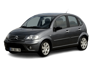
Below are the locations, diagrams, and photos of the power distribution boxes. Fuses responsible for the “Cigarette lighter” and “Fuel pump” circuits are highlighted in bold.
Engine Compartment Fuse Box

The distribution box is located on the right-hand side of the engine compartment. Its design and layout vary depending on the model year of the vehicle.
2005–2010 Models

General overview.
| Diagram | ||
|---|---|---|
| Type 1 | ||

|
||
| No. | Description | Rating (A) |
| 1 | Engine cooling fan | 20 |
| 2 | Horn | 15 |
| 3 | Windscreen washer pump motor | 10 |
| 4 | Headlamp washer pump | 20 |
| 5 | Engine management ECU | 15 |
| or | ||
| Fuel pump fuse (Petrol) | ||
| 6 | Electric power steering (EPS) | 10 |
| 7 | Battery supply / Power distribution | 10 |
| 8 | Starter motor control signal | 15 |
| 9 | ABS / ESP control module | 10 |
| 10 | Engine management unit (ECU) | 30 |
| 11 | Heater / Air conditioning blower motor | 40 |
| 12 | Windscreen wipers | 30 |
| 13 | Battery power supply (BSI) | 40 |
| 14 | - | - |
| 15 | Right high-beam headlamp | 10 |
| 16 | Left high-beam headlamp | 10 |
| 17 | Left dipped-beam headlamp | 15 |
| 18 | Right dipped-beam headlamp | 15 |
| 19 | Engine management ECU | 15 |
| 20 | 10 | |
| 21 | ABS / ESP system | 5 |
| MF1 | Engine cooling fan motor | 30/50 |
| MF2 | ABS / ESP control module | 30 |
| MF3 | 30 | |
| MF4 | Spare | 60 |
| MF5 | Spare | 60 |
| MF6 | Electronic Transmission Control Unit (TCM / SensoDrive) | 30 |
| MF7 | Spare | 40 |
| MF8 | Power steering control unit (EPS) | 80 |
| Type 2 | ||

|
||
| No. | Description | Rating (A) |
| 1 | Diesel water-in-fuel sensor | 20 |
| 2 | Horn | 15 |
| 3 | Windscreen washer pump | 10 |
| 4 | Headlamp washer pump | 20 |
| 5 | Fuel module (fuel pump fuse) | 15 |
| 6 | Electric power steering (EPS) | 10 |
| 7 | Engine coolant level sensor | 10 |
| 8 | Starter motor | 25 |
| 9 | ABS / ESP control module | 10 |
| 10 | Engine management actuators (ignition coils, solenoid valves, O2 sensors, injectors) – EVAP purge canister | 30 |
| 11 | Blower fan | 40 |
| 12 | Windscreen wipers | 30 |
| 14 | Secondary air injection pump (Petrol) / Diesel fuel heater | 30 |
| 15 | Right high-beam headlamp | 10 |
| 16 | Left high-beam headlamp | 10 |
| 17 | Left dipped-beam headlamp | 15 |
| 18 | Right dipped-beam headlamp | 15 |
| MF1 | Cooling fan | 30/50/70 |
| or | ||
| Automatic transmission unit | ||
| MF2 | ABS control module | 30 |
| ESP control module | ||
| MF3 | ABS control module | 30 |
| ESP control module | ||
| MF4 | Passenger compartment fuse box (BSI) | 30 |
| MF5 | 60 | |
| MF6 | Automated manual transmission (SensoDrive) | 30 |
| MF7 | Passenger compartment fuse box (BSI) | 40 |
| Diode module | ||
| MF8 | Electric power steering (EPS) | 80 |
2001–2005 Models
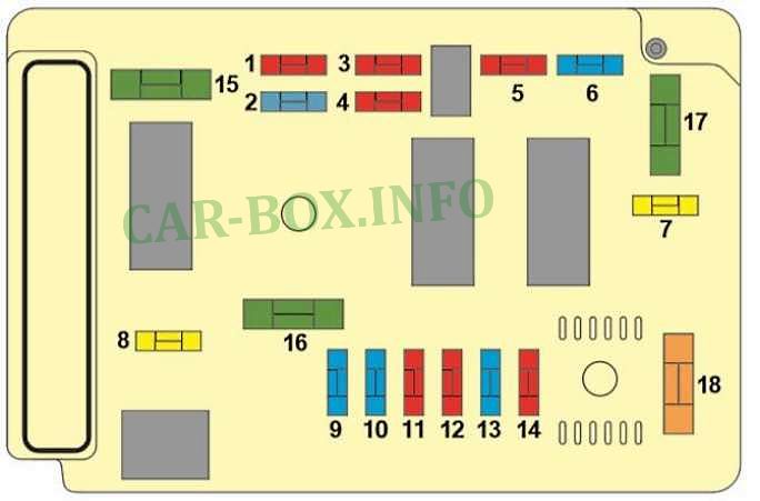
Engine compartment fuse allocation.
| Diagram | ||
|---|---|---|
|
||
| No. | Description | Rating (A) |
| 1 | Diesel engine preheating unit – Diesel water-in-fuel sensor – Vehicle speed sensor – Reversing lamps – Transmission ECU (Automatic / SensoDrive) | 10 |
| 2 | Fuel module (fuel pump fuse) | 15 |
| 3 | ABS / ESP Electronic Control Unit (ECU) | 10 |
| 4 | ECU (fuel injection system, power steering) – Sensors (coolant level, cruise control, brake pedal switch, clutch switch) – Transmission relays – Auxiliary heating unit | 10 |
| 5 | Front fog lamps | 15 |
| 6 | Headlamp washer pump | 20 |
| 7 | Engine control relay – Fuel injection ECU | 20 |
| 8 | Left dipped-beam headlamp | 15 |
| 9 | Right dipped-beam headlamp | 15 |
| 10 | Left high-beam headlamp | 10 |
| 11 | Right high-beam headlamp | 10 |
| 13 | Horn | 15 |
| 14 | Windscreen / rear window washer pump | 10 |
| 15 | Engine management actuators (ignition coils, solenoid valves, O2 sensor, injectors) – EVAP canister – Diesel fuel heater | 15 |
| 16 | Secondary air injection pump | 30 |
| 17 | Windscreen wipers | 30 |
| 18 | Electric cooling fan | 30/40 |
|
||
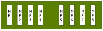
| MF1 | Cooling fan motor | 30 |
| MF2 | Anti-lock braking system (ABS) | 30 |
| MF3 | 30/50 | |
| MF4 | Built-in Systems Interface (BSI 1) | 60 |
| MF5 | 70 | |
| MF6 | Heated seats | 20 40 50 |
| MF7 | Ignition switch | 30 |
| MF8 | Electric power steering (EPS) | 80 |
Passenger Compartment Fuse Box
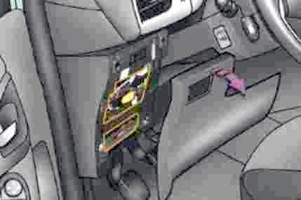
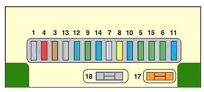
The passenger compartment fuse box (BSI) is located on the driver’s side of the lower dashboard, behind a removable plastic access cover. Like the engine compartment panel, its layout depends on the vehicle's model year.
2005–2010 Models

General overview of the Citroën C3 passenger compartment fuse box.
| Diagram | ||
|---|---|---|
|
||
| No. | Description | Rating (A) |
| 3 | Airbag system | 5 |
| 4 | Diagnostic connector (OBD) – DPF additive module – Clutch switch – Crankshaft position sensor | 10 |
| 5 | Rear power windows – Power sunroof | 30 |
| 6 | Windscreen washer pump | 30 |
| 8 | Digital clock – Steering wheel audio controls – Audio unit – Multi-function display | 20 |
| 9 |
|
30 |
| 10 | Anti-theft alarm system | 15 |
| 11 | Ignition switch – Diagnostic connector (OBD) | 15 |
| 12 | Airbag control unit – Rain and light sensor | 15 |
| 14 | Parking sensors (Parktronic) – Instrument cluster – Automatic climate control – Bluetooth® module | 15 |
| 15 | Central locking system – Deadlocking system | 30 |
| 17 | Heated rear window | 4 |
| 18 | PARK / CLIENT Shunt fuse | - |
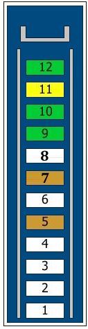
| Auxiliary Fuse Panel No. 2 | ||
|
||
| No. | Description | Rating (A) |
| 1 | Spare | |
| 2 | Spare | |
| 3 | Spare | |
| 4 | Spare | |
| 5 | Spare | |
| 6 | Spare | |
| 7 | Power sunroof | 5 |
| Power door mirrors | ||
| Front power windows | ||
| 8 | Spare | |
| 9 | Power soft-top (Pluriel) | 30 |
| or | ||
| Rear power windows | ||
| or | ||
| Spare | ||
| 10 | Rear power windows | 30 |
| or | ||
| Heated seats | ||
| or | ||
| Spare | ||
| 11 | Heated front seats | 20 |
| or | ||
| Spare | ||
| 12 | Rear power windows | 30 |
| Spare | ||
| Not used | ||
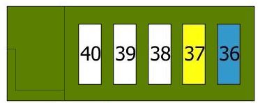
| Auxiliary Fuse Panel No. 3 | ||
|
||
| No. | Description | Rating (A) |
| 36 | Audio system (if equipped) | 15 |
| 37 | Heated seats / Power folding roof (if equipped) | 20/30 |
| 38 | Spare | |
| 39 | Spare | |
| 40 | Spare | |
2001–2005 Models
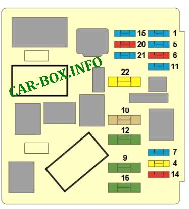
Passenger compartment fuse allocation.
| Diagram | ||
|---|---|---|
|
||
| No. | Description | Rating (A) |
| 1 | Diagnostic socket power supply – Towbar wiring harness – Navigation system | 15 |
| 4 | Automatic transmission ECU – Steering column stalk switch – Clock – Multi-function display – Navigation system – Anti-theft alarm unit – Audio unit | 20 |
| 5 | Anti-theft alarm siren | 15 |
| 6 | Diagnostic connector (OBD) – Crankshaft position sensor | 10 |
| 7 | Rain and light sensor – Anti-theft alarm control unit | 15 |
| 10 | Heated rear window – Heated door mirrors | 40 |
| 11 | Rear window wiper | 15 |
| 12 | Power supply circuit for sliding sunroof – Front power windows | 30 |
| 14 | Steering wheel paddle shifters – Airbag control unit (ECU) – Engine compartment fuse box | 10 |
| 15 |
|
15 |
| 16 | Central locking system Deadlocking system |
30 |
| 20 | Right brake light | 10 |
| 21 | Left brake light High-mounted third brake light |
15 |
| 22 |
|
20 |
Individual Relays
Several individual relays are located in the passenger compartment and engine compartment.

|
|
| R1 | Child safety door locks |
| R2 | Gearshift interlock control |
| R3 | Starter interlock relay |
| R4 | Engine cooling fan relay |

Is there a separate fuse for the courtesy light in the boot of a citroen c3 (second gen)?