
In 2010, the second-generation Citroën C4 (B7) was unveiled in Paris. Concurrently, the decision was made to discontinue the three-door hatchback, meaning the new model was initially produced exclusively as a five-door hatchback (the sedan was not officially introduced until late 2012). This guide provides a detailed look at the power distribution and fuse box diagrams for the second-generation Citroën C4 (PF2 platform; B7 code) covering the 2011, 2012, 2013, 2014, 2015, 2016, 2017, and 2018 model years.
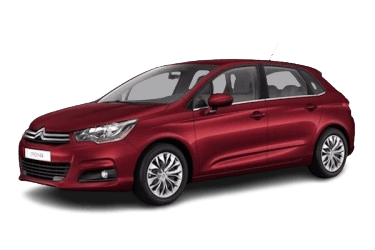
Here you will find the locations and photos of the power distribution modules. The fuses protecting the “Cigarette lighter” and “Fuel pump” circuits are highlighted in bold.
Engine Compartment
The engine compartment houses two power distribution boxes designed to protect the vehicle's electrical circuits.
Main Fuse Box
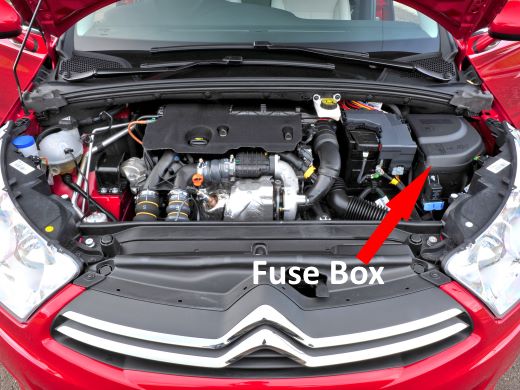
Located adjacent to the battery.
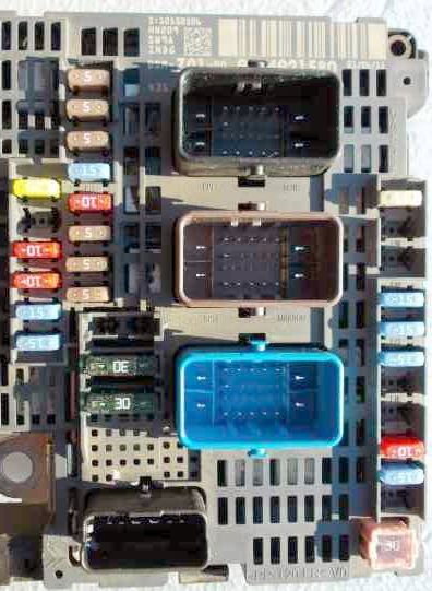
General layout.
| Diagram | ||
|---|---|---|

|
||
| No. | Circuit Description | Amperage (A) |
| F1 | Engine control module (ECM) | 15 |
| F2 | Cooling fan assembly (dual-speed) | 5 |
| F3 | Engine control module (ECM) | 5 |
| F4 | 5 | |
| F5 | Engine management and cooling fan control module | 15 |
| F6 | Engine control module (ECM) | 20 |
| Fuel pump and fuel level sending unit | ||
| F7 | Engine control module (ECM) | 10 |
| F8 | 10 | |
| F10 | Clutch pedal position (CPP) switch | 5 |
| Transmission control module (TCM) | ||
| Headlamps | ||
| F11 | Clutch pedal position (CPP) switch | 5 |
| Transmission control module (TCM) | ||
| Headlamps | ||
| F12 | Anti-lock braking system (ABS) | 5 |
| F15 | Data link connector (DLC) | 20 |
| Electronic power steering (EPS) | ||
| Engine coolant level sensor | ||
| Fuel additive pump | ||
| Built-in Systems Interface (BSI) | ||
| F17 | Data link connector (DLC) | 20 |
| Electronic power steering (EPS) | ||
| Engine coolant level sensor | ||
| Fuel additive pump | ||
| Built-in Systems Interface (BSI) | ||
| F19 | Windshield wiper motor (low / high speed) | 30 |
| F20 | Windshield washer fluid pump | 15 |
| F21 | Headlamp washer fluid pump | 20 |
| F22 | Horn | 15 |
| F23 | Right high-beam headlamp (halogen) | 15 |
| F24 | Left high-beam headlamp (halogen) | 15 |
| F26 | A/C compressor | 10 |
| A/C compressor clutch | ||
| or | ||
| A/C compressor | ||
| F27 | Left headlamp | 5 |
| F28 | Right headlamp | 5 |
| F29 | Starter motor | 25 |
| F30 | Engine control module (ECM) | 30 |
Additional Fuse Panel
An additional fuse block is located on the lower side of the main unit.

|
||
| No. | Circuit Description | Amperage (A) |
| F8 | Electronic power steering pump / Manual transmission module | 30 |
| F10 | Automatic transmission module | 5 |
| F11 | Shift interlock relay | 5 |
| F12 | Automatic transmission module | 15 |
| F18 | Gear selector lever | 5 |
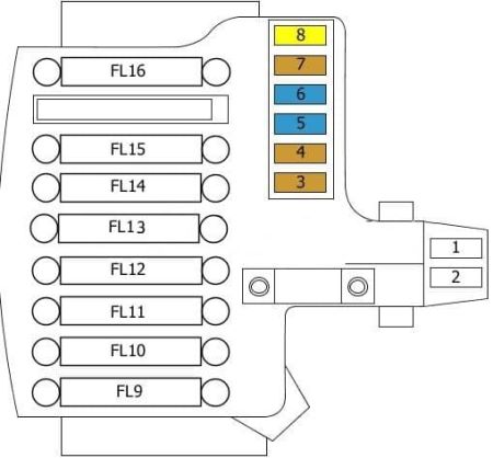
Battery-Mounted Fuse Box
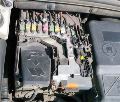
High-current fusible links are located directly on the battery distribution block.
| Diagram | ||
|---|---|---|
|
||
| No. | Circuit Description | Amperage (A) |
| FL9 | Built-in Systems Interface (BSI) | 60 |
| FL10 | Electronic power steering (EPS) | 80 |
| FL11 | Transmission control module (TCM) | 30 |
| FL12 | Cooling fan motor | 60 |
| FL13 | Built-in Systems Interface (BSI) | 60 |
| FL14 | Glow plug control module | 70 |
| FL15 | Protection relay module 3 | 100 |
| FL16 | Not used | |
| 1 | Not used | |
| 2 | Not used | |
| 3 | Battery charge status sensor | 5 |
| 4 | Transmission control module (TCM) | 5 |
| 5 | Data link connector (DLC) | 5/15 |
| 6 | Transmission control module (TCM) | 15 |
| 7 | ABS and ESP control modules | 5 |
| 8 | Rear 12V auxiliary power outlet | 20 |
Passenger Compartment
The cabin houses two additional power distribution boxes for interior electrical circuits.
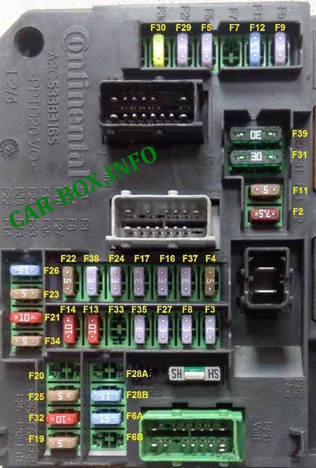
Main Interior Fuse Box
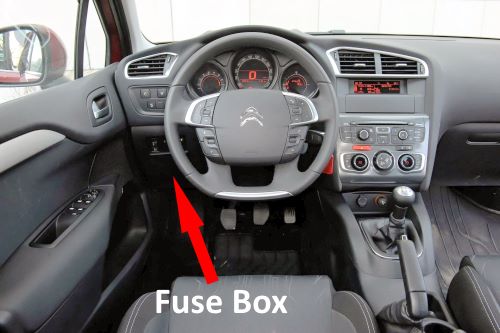
This fuse box is located on the driver's side of the dashboard, concealed behind a plastic trim panel.

To access the fuses, unclip the cover by pulling the top right corner, followed by the top left, and then remove the panel entirely.
| Diagram | ||
|---|---|---|
|
||
| No. | Circuit Description | Amperage (A) |
| F2 | Data link connector (DLC) | 7.5 |
| F3 | Ignition switch | 3 |
| or | ||
| Immobilizer / “START/STOP” button | ||
| F4 | Telematics control unit | 5 |
| F5 | Tire pressure monitoring system (TPMS) | 3 |
| or | ||
| Remote keyless entry receiver | ||
| F6A | Audio system / Radio | 15 |
| F6B | ||
| F7 | Interior power distribution box | 15 |
| or | ||
| Keyless entry and start system module | ||
| F8 | Anti-theft alarm siren and control module | 3 |
| F9 | Steering wheel control module | 3 |
| F11 | Electronic Stability Program (ESP) control module | 5 |
| F12 | Brake pedal position (BPP) switch | 15 |
| F13 | Front cigarette lighter / 12V auxiliary power outlet | 10 |
| F14 | Trunk cigarette lighter and 12V auxiliary power outlet | 10 |
| F16 | Glove box illumination, rear reading lamps. | 3 |
| F17 | Vanity mirror illumination, front reading lamps. | 3 |
| F19 | Instrument cluster | 3 |
| F21 | Multifunction switch | 10 |
| Multiplex control module | ||
| or | ||
| Audio and climate control panel | ||
| F22 | Parking assist module | 10 |
| Instrument cluster | ||
| Multifunction display | ||
| F23 | Engine compartment fuse box 1 | 5 |
| F24 | Rain and ambient light sensor | 3 |
| F25 | Supplemental Restraint System (SRS) / Seat belt pretensioners | 3 |
| F26 | Interior fuse box | 15 |
| F27 | Brake pedal position (BPP) switch | 3 |
| F28 | Audio system (optional accessories) | 15 |
| F29 | Steering wheel controls | 3 |
| F30 | Rear window wiper motor | 20 |
| F32 | Central locking system | 30 |
| F32 | High-fidelity audio amplifier | 10 |
| F35 | Seat belt warning module | 3 |
| Electronic power steering (EPS) relay | ||
| F37 | Headlamp leveling system | 3 |
| Rearview mirror / Windshield wipers | ||
| Climate control module | ||
| F38 | Auto-dimming rearview mirror / Headlamp leveling switch | 3 |
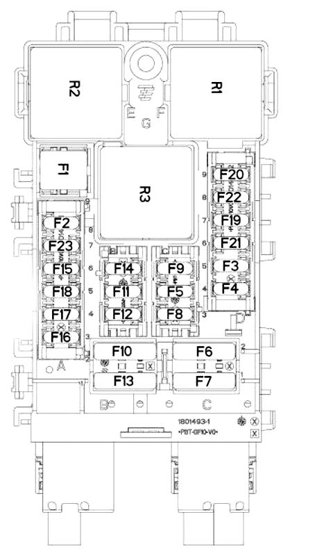
BFH3 Fuse Panel

The BFH3 fuse module is located directly below the main interior unit.
| Diagram | ||
|---|---|---|
|
||
| No. | Circuit Description | Amperage (A) |
| F1 | Rear window defogger | 40 |
| F2 | Heated exterior mirrors | 7.5 |
| F3 | Passenger compartment fuse box (5A for taxi specification) |
15 |
| F4 | 12V auxiliary power outlet for multimedia | 15 |
| F5 | Rear power window motors | 30 |
| F6 | Front power window motors | 30 |
| F7 | Heated seats | 2 |
| F8 | HVAC blower motor | 20 |
| F9 | Power tailgate release | 30 |
| F10 | Left seat belt retractor | 40 |
| F11 | Trailer tow module | 5 |
| F12 | Power driver’s seat and massage function | 30 |
| F13 | Right seat belt retractor | 40 |
| F14 | Power passenger seat and massage function | 30 |
| F15 | Power panoramic roof blind | 25 |
| F16 | Driver’s door window / exterior mirror multiplex control module | 5 |
| F17 | Exterior mirror courtesy lighting and memory module | 10 |
| F18 | Audio amplifier | 25 |
| F19 | Spare | |
| F20 | Power tailgate | 7.5 |
| F21 | Keyless entry and start module | 3 |
| F22 | 230V AC power outlet | 20 |
| F23 | Not used | |
| R1 | 230V AC power outlet relay | |
| R2 | 12V auxiliary power outlet relay | |
| R3 | Not used | |

Super przydatne informacje Dziękuję! Nawet płatny HajnesPro nie pomógł tylko info o paru bezpiecznikach reszta brak informacji /SUPER POLECAM